The advanced settings are divided into two tabs; Settings 1,
Settings 2,
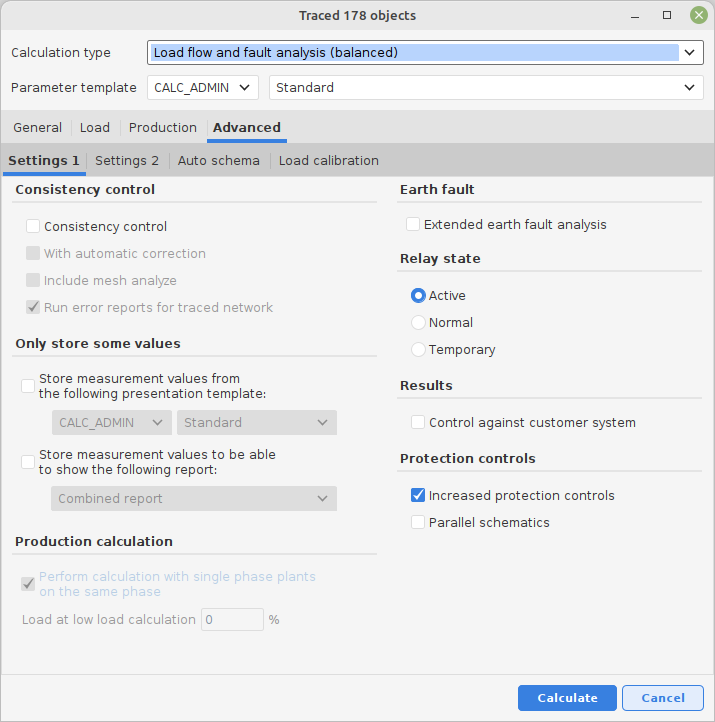
1 Consistency control
A special control emphasized on finding errors and problems that can have a negative impact on a network calculation.
For more information about the scope and conditions for this control, see appendix: Consistency Control
When the check box for consistency control is checked, two more alternatives will be selectable;
With Automatic Correction (combined with Consistency Control checked).
This is a special feature to try to identify and automatically try to correct errors/problems and thereafter execute a load flow calculation. The function is trying to get the calculation data in the network as “good” as possible, in order to be able to perform a calculation. The actions performed can be found in the error list.
The purpose of this function is to give support when searching for major errors in the network when calculation fails. If the calculation is successful using this function you will find good support for correcting the network data, based on the actions this feature has performed.
Include mesh analyze
This is a help function which tries to identify meshes, substations joined in meshes and highlight connected conductors which builds the meshes or connects substations.
For more information about the scope and conditions for this control see appendix: Consistency Control
Run error reports for traced network
A help function that runs a number of "standard troubleshooting reports" in series for the tracked network.
The reports currently running are: (may be added to more on request)
•Connections that violate connection rules.
•Object that lack graphic.
•parent links that violate rules.
•Errors in stations.
2 Only store some values
This function makes it possible to limit the result volume that is suppose to be loaded into the database. There are two alternatives that can be combined. Some identities and keys is always loaded regardless of the extent specified.
A: Store measurement values from the following presentation template.
Base the extent on a stored presentation template. Only the terms of results that exists in the presentation template is loaded into the database.
B: Store measurement values to be able to show the following report.
Base the extent on one or several reports and its content. Only the results necessary to generate each report is loaded into the database.
3 Earth fault
Select the check box to create an extended earth fault analysis.
When performing medium voltage calculations on impedance earthed neutral point networks, it is possible to receive a special report for an extended earth fault calculation.
See appendix: Earth fault calculation considering conductor capacitances
4 Relay state
Select the state that you wish to use for the relay protection:
Active: The current relay protection state is used.
Normal: Normal state is used for all relay protections.
Reserve: The reserve state is used for all the relay protections.
5 Distributed generation calculation
This field belongs to distributed generation calculations and is described in the appendix distributed generation calculation.
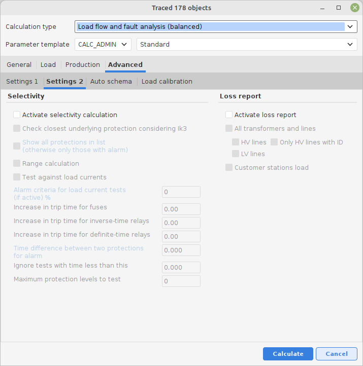
6 Activate selectivity calculation
A function for selectivity analysis and range calculation for protection devices.
In order for the selectivity analysis to be executed, the check box Activate selectivity calculation must be checked and some mandatory values must be entered.
In the same calculation it is also possible to get information about overload and range presentation.
The result from the selectivity calculations is presented both in the log for the network calculation as well as in a separate Extra report.
See the appendix: Selectivity protection analysis for more information about the scope and conditions of this control.
7 Loss report
Create a specific loss report that is presented in an Excel-table.
Check the check box Activate loss report to activate the other alternatives (All transformers and cables, Customer stations load).
Unbalanced network calculations can for instance be used when calculation of street lighting networks that are completely documented regarding conductor phases and phase loads.
This type of calculation can also be used on low and medium voltage networks where the loads are not symmetrically attached. In this case it is also necessary to provide a correct network documentation regarding conductor phases and phase loads.
With this tool you can also easily get an understanding of the consequences of different types of uneven loads in the network.
See appendix: Unbalanced calculations for a short introduction.
8 Motor start objects
This will allow you to place one or several motor objects in a map / schematic presentation. Connect with a switch or a short conductor to the node/point/bus bar that the motor is supposed to be tested in. Several optional test motors can be added to the same node since they are tested separately, independent of each other.

After a calculation trace, a list containing all traced motors will be presented in the tab Advanced settings 2.
Select the motor or motors that should be tested according to voltage drop conditions at motor starts. The result is presented after the calculation under the menu choice Extra report in the result archive.
For more information about the scope and conditions of this control, see appendix: Motor start
Auto generated schema
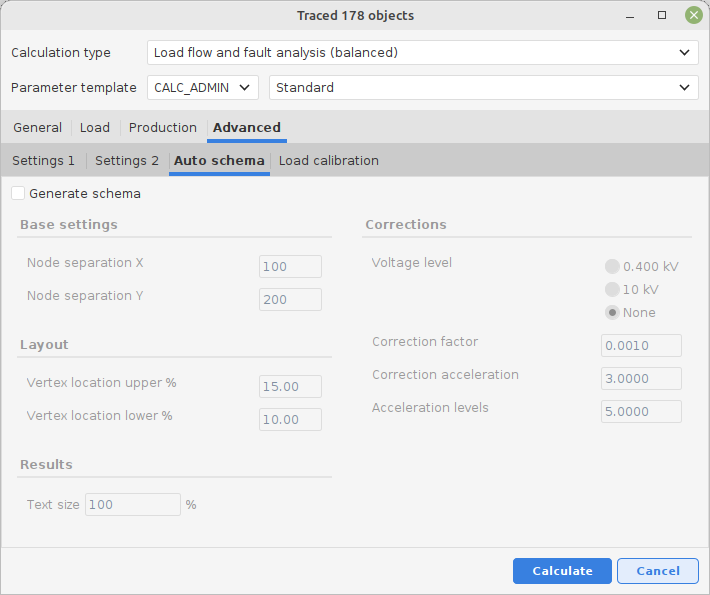
If this alternative is checked, a presentation of a schematic calculation should be generated when the calculation has been done. It is possible to select a schematic presentation, a standard presentation or both for the calculation results.
The result presentation content can be configured by using the administration tools.
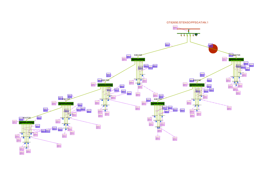
Example of a schematic presentation:
Load calibration
If measured network currents are available, a load calibration can be done against these measured values assuming all other conditions are fulfilled. The function is activated by using the check box Activate load calibration.
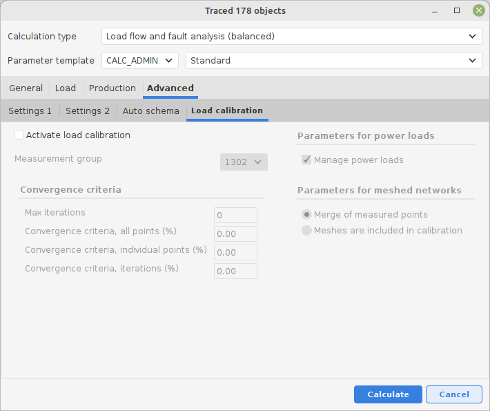
An extra report will be presented after a calibration calculation has been done. Right-click on the calculations row in Results/Administration and select Show extra report.
Example:
--------------------------------------------------------------------------------------------------------------
LOAD CALIBRATION
--------------------------------------------------------------------------------------------------------------
Measured point : ST13/LST13-B Current : 95.0 A
Measured point : ST13/LST13-B Current : 46.0 A
Measured point : ST13/LST13-B Current : 25.0 A
Round : 1 Total difference : 27.24 %
Measured point : ST13/LST13-B Calculated current : 85.87 A Difference : 9.61 %
Measured point : ST13/LST13-B Calculated current : 46.32 A Difference : 0.69 %
Measured point : ST13/LST13-B Calculated current : 42.86 A Difference : 71.44 %
Round : 2 Total difference : 1.74 %
Measured point : ST13/LST13-B Calculated current : 95.28 A Difference : 0.29 %
Measured point : ST13/LST13-B Calculated current : 45.84 A Difference : 0.34 %
Measured point : ST13/LST13-B Calculated current : 23.85 A Difference : 4.59 %
--------------------------------------------------------------------------------------------------------------
See appendix Load Calibration for further information