Production can consist of solar panels or wind turbines connected to 0.23- or 0.4 kV networks.
|
Also single-phase plants are documented with respect to phase to phase voltage. |
The object is connected to a delivery point, for example through a conductor or a switch. In an add on module there is also a custom calculation routine for production to calculate its impact on power quality in the network. This is based largely on the reports MICRO and AMP.
Attribute form
In the form, enter the ID and the GS1-code for the customer facility that the plant is connected to. When a GS1 code is entered, the ownership information related to the current customer facility is shown. Also serial number, manufactured date and notes can be entered if desired.
To enable network calculations with production also enter fields for Network calculation data. For solar panels set the active power (kW), power factor, phase code (for example, L1-N or L1-L1-L3-N), and if the unbalanced protection is installed (applies to three-phase connection). If unbalance protection is missing for a three-phase connected plant the calculation will be performed as if single phase connected.
For batteries, set the active charging power (kW), active discharging power (kW) and optionally max reactive power (kVAr) .
For wind turbines, enter the same values as for solar panels, as well as values under the tab Windpower. There the type of generator connection is entered, directly connected, doubly fed induction generator (DFIG) or full power converter. Instead of the power factor, the reactive power can be set. Maximum active and reactive power refers to the powers that the wind turbine does not exceed regardless of weather conditions (measured as a ten second mean value).
|
The reactive power production is the scope. Consumption of reactive power hence has a negative value. |
To include the impact of the power plant on short circuit currents in the network, enter short circuit values.
In the add on module for Distributed generation also flicker calculations can be performed, for this the flicker fields need to be entered.
To be able to perform these calculation the N120 is specified, which relates to the maximum number of allowed connections during a two-hour interval, as well as the turbine used. The code list for the turbine stores flicker constant, flicker step factor and the voltage change factor for the turbine. All constants are specified for four different short circuit angles, and the one that most closely match that of short circuit angle in the current delivery point will be used in the calculations.
Flicker values
For flicker calculation N120 is specified (maximum number of starts during a two-hour interval),
and turbine type, which indicates the values specific to the turbine type. These values consist of:
-Cf - flicker coefficient.
-Kf - flicker step factor.
-Ku – voltage change factor.
All stated for short circuit angles 30°, 50°, 70° och 85°.
If no values are stated, then the extreme values ku=3 and cf=20 will be used for the calculations.
Perform calculations for production facilities
The default when performing calculations is to ignore production. To consider these facilities check the box Include production in the Production tab in the Calculation dialog. To include batteries, check the box Include energy storage (batteries) and choose whether the batteries should be charging or discharging. The percentage value can be changed to scale the input from production/battery facilities.
To consider single phase connected facilities an unbalanced load- and fault analysis calculation should be performed. For regular load flow and fault analysis calculations all components are assumed to be three-phase.
For more information about unbalanced calculations, see appendix Unbalanced calculations.
To use the special calculation for production included in the add on module distributed generation, change the Calculation type in the Network calculation window to Production calculation. After changing the type, start values from a reference calculation are retrieved, and other settings can be entered.
During a Production calculation two calculations are performed, one with 100% consumption and 0% production, the other with 0% consumption and 100% production. The results from these two calculations are then compared in the results.
Batteries are included in a Production calculation. The battery is assumed to be charging during the 100% consumption and 0% production calculation, meaning that the Active charging power is added to the consumption at the delivery point. In the 0% consumption and 100% production calculation, the battery is assumed to be discharging, meaning that the Active discharging power is added as a power source at the delivery point.
Settings for this calculation can be found in the Advanced settings tab.
Alternative |
Explanation |
Perform a calculation with single phase plants on the same phase |
All single phase facilities are transferred to the same phase in the calculation (otherwise the documented phase code is used). |
Load at low load calculation |
Percentage (of power to be used in low load calculation based on Velander calculations) |
Results from a production calculation
The result from normal calculation, where production has been included, can be analyzed as usual by for example presentation of the result in the map, right-click on an object and select Calculated Values > All calculations.
The calculation procedure in the add on module contains the following in addition to the standard result:
-Max voltage.
-Min voltage.
-Difference in max and min voltage.
-Unbalanced voltage.
-Voltage change during connection at current delivery point.
-Voltage change during connection at closest point of common connection to other customers.
-Flicker during operation (wind power).
-Flicker during start-up (wind power).
-Voltage change at start up process (wind power).
After a calculation the results are stored. To obtain a simple overview on how the power quality is influenced by the production there is a specific report for this purpose. There is also a simplified report listing only production objects.
Calculations performed in the add on module
The calculations are mainly based on the reports MIKRO and AMP from Svensk Energi. For the calculations of max/min voltage two separates network calculations are performed, the first with the assumption of maximum load/no production, the other for maximum production/no load.
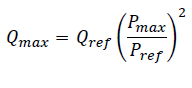
For wind turbines, the maximum active and reactive power are used for calculations if specified. For direct-connected generators the maximum reactive power is estimated according to the following equation if not specified manually:
Voltage change during connection is calculated using the following equation:
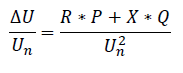
The networks earth fault impedance and phase voltage are used for single phase facilities. For three phase connected facilities the short circuit impedance and phase to phase voltage is used. The calculation is performed both at the current delivery point and the closest upside point of common connection (for example bus in cable pillar or substation)
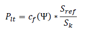
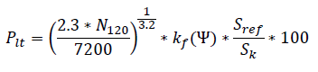
Sref is the apparent rated power (kVA) of the wind turbine. Sk is the short circuit power of the network (kVA). Flicker at operation is calculated using the following equation:
Flicker at startup is calculated using the following equation:
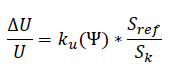
The voltage change at start up process of wind power turbine is calculated using the following equation: