Selectivity analysis
Options
The selectivity control is only performed if the check-box Activate selectivity calculation is checked in the tab “Advanced settings > Advanced settings 2”.
In this case an extra analysis will be performed after the ordinary calculations. This analysis can be very resource demanding for large networks, and hence not recommended to run this too often. The analysis is based on a normal load flow calculation.
The result from the selectivity analysis is presented in the error-/warning-list as well as in an extra-report.
Short description of the form settings.
Check-boxes
•Check closest underlying protection considering Ik3.
| If there is any protection directly connected below the fault location also this protection will be tested against maximum fault current. |
•Show all protections in list (otherwise only those with alarm).
| A printout of protection information regarding every single protection included in the analysis. If not checked only information about protections that have received alarms will be shown. Recommended! |
•Range calculation.
| A calculation of the range for each protection will be performed. For fuses and inverse time relays the times stated in the “fault-current tab of calculation parameters” will be used. For constant time relays the longest time step stated will be used. |
•Test against load currents.
| In order for the test to be performed, a percentage must be set for the alarm condition. |
Other values / constants.
•Alarm criteria’s for load current tests (if active) %.
| Alarm is obtained when the percentage load exceeds this value. Fuses are tested against rated current, constant time relays are tested against lowest set primary current, and inverse time relays are tested against the start current. |
•Increased time for fuses tripping time.
| A possibility to give a security factor for fuses. |
•Increased time for inverted relays trip time.
| A possibility to set a security factor or other type of added template time for inverse time relays, i.e. extra time caused by a breakers time-delay. |
•Increased time for constant relays trip time.
| A possibility to set a security factor or other type of added template time for constant time relays, i.e. extra time caused by a breakers time-delay. |
•Time difference between two protections for alarm.
| Alarm is obtained when the tripping times between two close protections is less than the stated time for the same fault location. Note that the time difference for non selectivity is negative. This means that a value supposed to give an alarm for non selectivity must also be negative. |
•Ignore tests with times less than this.
| A limit for when a protection should be included in a test. If obtained tripping times are smaller than this time then it will not be included in the test. |
•Maximum protection levels to test.
| For every single fault location this number of protections in feeding order will be tested against each other. The test can only be performed in a network including transformers (more than one voltage level). |
Execution
Only radial parts of the network can be managed correctly.
Faults are simulated in every node point, bus bars, joints, etc.
The fault types that can be managed are three phase short circuit (Ik3) for both LV and MV networks, two phase short circuit (Ik2) for MV networks, and short circuit for phase/neutral (Ij) for LV networks.
For every fault location tripping times are calculated for protections that are located “up-streams”, and in as many levels as has been requested.
If a transformer is passed up-streams, the fault currents are recalculated to the higher voltage level and the selectivity-test continues up-streams until either the maximum level has been reached, or a second transformer is passed.
Note! that the transformers must have a correct vector group specified, in order for the re-calculation over the transformer to be performed.
If parallel sections or transformers holds protection the fault currents will be distributed correctly in the parallel sections and a correct tripping time is obtained for each protection.
Presentation of result
Selectivity result
Extract from the “extra report” requested from the result archive using the right-click-function.
Example. See explanations below.
Explanation of the selectivity list.
Alarm header.
----------------------------------------------------------------------------------------------------------------------------------------------------------------------------------------------------------------------
<120> selectivity alarms found Type : Sel.
<32> overload alarm found Type : Ovl.
----------------------------------------------------------------------------------------------------------------------------------------------------------------------------------------------------------------------
Total number of found alarms of the type Sel = selectivity alarms, Ovl = overload alarms.
Display of participating protections. Either all, or only protection with alarms depending on choice. One protection object per row.
----------------------------------------------------------------------------------------------------------------------------------------------------------------------------------------------------------------------
37 ToSi Bay <SST004/10> - <*> Fuse <IFÖ UNI/35.0 A>Load = 401.5 A :1147.2 % Alarm <-Ovl-Sel->
39 ToSi Cond <CP0029> - <CP0030> Fuse <IFÖ UNI/20.0 A>Load = 330.0 A :1650.2 % Alarm <-Ovl-Sel->
43 FrSi Cond <CP0031> - <DPU00094> Fuse <IFÖ UNI/63.0 A>Load = 87.6 A :139.0 % Alarm <-Ovl-Sel->
45 FrSi Cond <CP0030> - <DPU00091> Fuse <IFÖ UNI/63.0 A>Load = 5.9 A :9.3 % Alarm <--Sel->
49 FrSi Cond <CP0029> - <DPU00089> Fuse <IFÖ UNI/63.0 A>Load = 25.7 A :40.8 % Alarm <--Sel->
57 ToSi Bay <SST004/05> - <*> Fuse <IFÖ UNI/20.0 A>Load = 374.0 A :1870.0 % Alarm <-Ovl-Sel->
58 FrSi Cond <CP0033> - <DPU00100> Fuse <IFÖ UNI/35.0 A>Load = 136.6 A :390.3 % Alarm <-Ovl-Sel->
72 FrSi Trf <N1-T2> - <*> Fuse <GEVEA/16.0 A>
77 FrPa1 Cond <KS3> - <KS4> Fuse <IFÖ/50.0 A>
----------------------------------------------------------------------------------------------------------------------------------------------------------------------------------------------------------------------
Description of records
37,39,43,.... Sequential number as reference to the protection in the result part of the list and in the network calculation log.
FrSi, ToSi, FrPa1. Code for positioning of protection. Fr = from side, To = to side, Si = the protection is placed in a single section, Pa1 = the protection is placed in a parallel section, 1 = serial number for the incoming parallel sections.
Bay, Cond, Trf. Type of object which the protection concerns. Bay, conductor, transformer.
<SST004/10> - <*>. Bay ID or transformer-ID.
<<CP0029> - <DPU00089>. From-point and to-point ID for the conductor section.
Then follows protection data
Inverse time Relay M :1000.0/- Normal Inverse Str.I:50.0 k:0.1. Inverse time relay with the following settings: Instantaneous current = 1000 A, Character = normal Inverse, Start current = 50 A, Scaling factor = 0.1.
Constant time-relay M :2500.0/0.1 P1 :200.0/1.4 P2 :50.0/2.7. Constant time relay with the following settings: Instantaneous current = 2500 A and 0.1 sec, Primary step 2 current = 200A and 1.4 sec, Primary step 2 current = 50A and 2.7 sec.
Fuse <TELEBERT/25.0 A>. Fuse with the type = TELEBERT and rated current = 25 A.
<R-70-F02>-<BR-70-F0>. For relays also the Relay ID and the ID for the breaker where the measurement is located will be shown.
Printout of the selectivity alarm
----------------------------------------------------------------------------------------------------------------------------------------------------------------------------------------------------------------------
Fault point <DPU00019> Ik3 :812.9 Ij : :269.5 Upside nearest transformer :Ik3 :16.7 Ij : :3.7
----------------------------------------------------------------------------------------------------------------------------------------------------------------------------------------------------------------------
For every point where faults have been simulated and at least one selectivity alarm has been found, fault-currents and ID for the point is printed. For a MV point the Ik3 and Ik2 are printed, and for a LV point the Ik3 and Ij are printed. If the nearest overlying transformer is completely documented, then the fault-currents will be re-calculated to the higher voltage-level and presented.
----------------------------------------------------------------------------------------------------------------------------------------------------------------------------------------------------------------------
External prote.dev.up : Fuse <IFÖ UNI/35.0 A> No :211 Time :0.3148 Unselective against down Fuse <IFÖ UNI/63.0 A> No :224 Time :6.8786 Type :Ij Diff :-6.563823
External prote.dev.up : Fuse <IFÖ UNI/35.0 A> No :211 Time :0.0227 Unselective against down Fuse <IFÖ UNI/63.0 A> No :224 Time :0.0737 Type :Ik3 Diff :-0.051033
----------------------------------------------------------------------------------------------------------------------------------------------------------------------------------------------------------------------
Detailed information about alarms. For every alarm one row is printed containing information about the two controlled protections.
External prote.dev.up: The protections are not in the same section. Up: Is located adjacent to the upper side in the feeding order. If the alarm covers protections in the same section then Internal protection… is printed.
Fuse <IFÖ UNI/35.0 A> No :211 Time :0.3148. Description of the protection that is located up-streams relative the other protection. No:224 refers to a protection earlier in the list.
Time: 0.0123 is the tripping time for the fault-current.
Unselective towards down Fuse <IFÖ UNI/63.0 A> No :224 Time :6.8786. Description of the other protection that is located down-streams relative the first protection.
Type: Ij / Type: Ik3 / Type: Ik2. Type of fault current that this alarm concerns.
Diff:-6.563823. The time difference between the tripping times for the two protections. A negative value means that the protection up-streams is activated earlier than the protection down-streams.
Printout of the network calculation log for the selectivity alarm.
In order to identify the protection alarms or ranges that are obtained, a dialog presenting the analysis result is displayed.
To view detailed information a row in the list is selected and then Highlight all to get information about which protections or nodes are regarded.
Over Load results
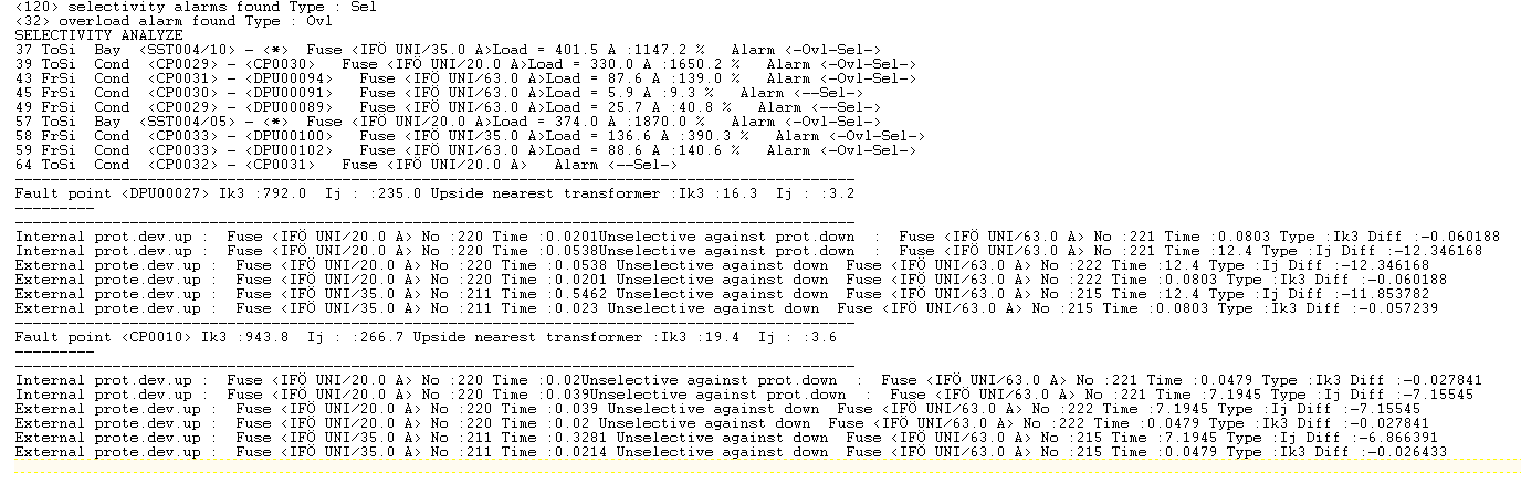
Example where the control of the overload is activated.
----------------------------------------------------------------------------------------------------------------------------------------------------------------------------------------------------------------------
<120> selectivity alarms found Type : Sel
<32> overload alarm found Type : Ovl
SELECTIVITY ANALYZE
37 ToSi Bay <SST004/10> - <*> Fuse <IFÖ UNI/35.0 A>Load = 401.5 A :1147.2 % Alarm <-Ovl-Sel->
39 ToSi Cond <CP0029> - <CP0030> Fuse <IFÖ UNI/20.0 A>Load = 330.0 A :1650.2 % Alarm <-Ovl-Sel->
43 FrSi Cond <CP0031> - <DPU00094> Fuse <IFÖ UNI/63.0 A>Load = 87.6 A :139.0 % Alarm <-Ovl-Sel->
45 FrSi Cond <CP0030> - <DPU00091> Fuse <IFÖ UNI/63.0 A>Load = 5.9 A :9.3 % Alarm <--Sel->
49 FrSi Cond <CP0029> - <DPU00089> Fuse <IFÖ UNI/63.0 A>Load = 25.7 A :40.8 % Alarm <--Sel->
57 ToSi Bay <SST004/05> - <*> Fuse <IFÖ UNI/20.0 A>Load = 374.0 A :1870.0 % Alarm <-Ovl-Sel->
58 FrSi Cond <CP0033> - <DPU00100> Fuse <IFÖ UNI/35.0 A>Load = 136.6 A :390.3 % Alarm <-Ovl-Sel->
59 FrSi Cond <CP0033> - <DPU00102> Fuse <IFÖ UNI/63.0 A>Load = 88.6 A :140.6 % Alarm <-Ovl-Sel->
----------------------------------------------------------------------------------------------------------------------------------------------------------------------------------------------------------------------
Description of the list
----------------------------------------------------------------------------------------------------------------------------------------------------------------------------------------------------------------------
<32> overload alarm found Type : Ovl
----------------------------------------------------------------------------------------------------------------------------------------------------------------------------------------------------------------------
Alarm <-Ovl-Sel->. The alarm type "Ovl-Sel" = over load and selectivity.
Load = 87.6 A :139.0 %. The load-level in A and in % of the overload protection rated value.
Range results
Results of the range of protection devices are only presented in the network calculation log.
For every protection device a row is printed that can be selected for identification in the schematic or map presentation. The following row(s) shows the object(s) that are end points for the range of this protection device.