The foundation for Network calculations or the generated Auto schema is created by tracing the network.
1.In the menu bar, select Analyzer > Trace menu…. The dialog box Trace menu opens.
|
Prior to a tracing, the desired extent of tracing/net calculation must be defined. |
Options in Trace menu
Trace method
There are five methods to mark the start of tracing in the map:
Select feeding point |
This option requires to also set the feeding point for the calculation. If there are network objects connected to the feeding point that should not be included in the calculation, they must be excluded. This is done by setting stop objects that isolates network parts not to be included. |
Select bay in Sec. substation |
Select a network object within the requested LV feeder when starting the trace. The highest selected voltage level must be the same as the bus bar at the start of the feeder, which normally is the lower side of the secondary substation. This means that no secondary substation transformers will be included in the trace. The calculation will include a feeder with a connected bus bar as a start point. The calculation also includes the underlying sub network if found. |
Select bay in Primary substation |
Select a network object within the requested MV feeder when starting the trace. The highest selected voltage level must be the same as the bus bar at the start of the feeder, which normally is the lower side of the primary substation. This means that no primary substation transformers will be included in the trace. The calculation will include a feeder with a connected bus bar as a start point. The calculation also includes the underlying sub network if requested by the voltage level settings. |
Select object |
Select a network object within the requested area at the start of the trace. The extent of the network is primarily decided by the combination of voltage level and stop type. If several possible feeding points can be found by the trace you will be asked to specify which to use or define more stop objects. |
Select bay in Switchstation |
Select a network object within the requested LV feeder when starting the trace. The highest selected voltage level must be the same as the bus bar at the start of the feeder, which normally is the lower side of the secondary substation. The calculation will include a feeder with a connected bus bar as a start point. The calculation also includes the underlying sub network if found. |
Voltage level (kV)
Select the voltage levels that should be part of the calculation. The voltage level work together with Stop types and Trace method.
Example: If the highest voltage level is 40 kV and the trace method Select object is selected, the suggestion for Stop type will be Bus bar 40 kV. This will then be seen as the feeding point for the calculation.
Usage state
Select the type of states that should be included when performing the trace. Normally the states Planned, Designed and In use are used.
Operational mode
Select which operational mode should be used in the calculation. There are two options:
Normal |
This mode used for documenting the network. |
Actual |
Temporary switching mode. If dpPower Analyzer is connected to a SCADA system the Actual switch status value will be received from the SCADA system. |
Stop types
Select object types where the trace should stop.
Define the Feeding Point that you want for the tracing method. Select object, Select bay in primary station or Select bay in sec. substation. Normally an object type will automatically be suggested by the selected voltage level.
Example: If the highest voltage level is 20 kV and the tracing method Select object is selected, then Substation Bus bar 20 kV will be suggested as a stop type for the trace.
Stop types can also be set manually. This can be valuable when you want to perform calculations on a smaller part of a large network with the same voltage level.
1.Select stop type and voltage level.
2.Press Add.
|
It might be hard to find a unique stop type when entering the stop type manually. If you for instance select a Cable pillar Bay as a stop object, a list of all connected cable pillar bays on the used voltage level will be shown. To stop tracing at a specific object, enter the object instead as a stop object in the box below. |
Stop objects
Select single objects where the trace should stop. This method is easier and more distinct to use than the manual selection of the stop type.
If the tracing method Select feeding point has been selected, unwanted parts of the network should be blocked by stop objects. For example, it is possible to prevent one or more outgoing feeders from a substation to participate in the trace in order to perform the calculation for only one or just a few feeders.
Even when another tracing method has been selected, the search can be restricted by adding stop objects. This can be useful when you want to perform calculations on a smaller part of a large network with the same voltage level. Switches are the best objects to select as a stop objects.
1.Press Add.
2.Select an object in the map. The object is shown in the field Stop object. In the map, the object is temporarily highlighted with red color. The color disappears when the tracing for calculation or auto schema starts.
Bypass switches
Used for defining specific switches where the trace should continue, even if they are disconnected.
1.Press Add.
2.Select an object in the map. The object is shown in the field Bypass switches. In the map, the object is temporarily highlighted with green color. The color disappears when the tracing for calculation or auto schema starts.
Other settings
Save to object list |
Saves the result of the trace and can later be used as a filtering function in reports and queries. |
Include street lighting network |
Includes the street lighting network in the trace. |
Start a trace
When all the selections have been made:
1.Press Trace to start a network calculation or press the triangle next to Trace and select Trace for auto schema to generate a schematic map for the traced network.
2.Select the starting point for the trace in the map/schema by selecting an object and confirm. The trace will start. When the trace is done, the traced network is highlighted and the dialog for network calculation or auto schema opens.
If you need to zoom in on the traced network:
1.In the menu bar, select Window > Fit view > Highlighted.
Trace the network - Use case example
A normal trace of a substation 20/0.4 kV. In the substation, by the use of stop objects, some of the 0.4 kV network will be blocked and only the lower part of the network will be traced.
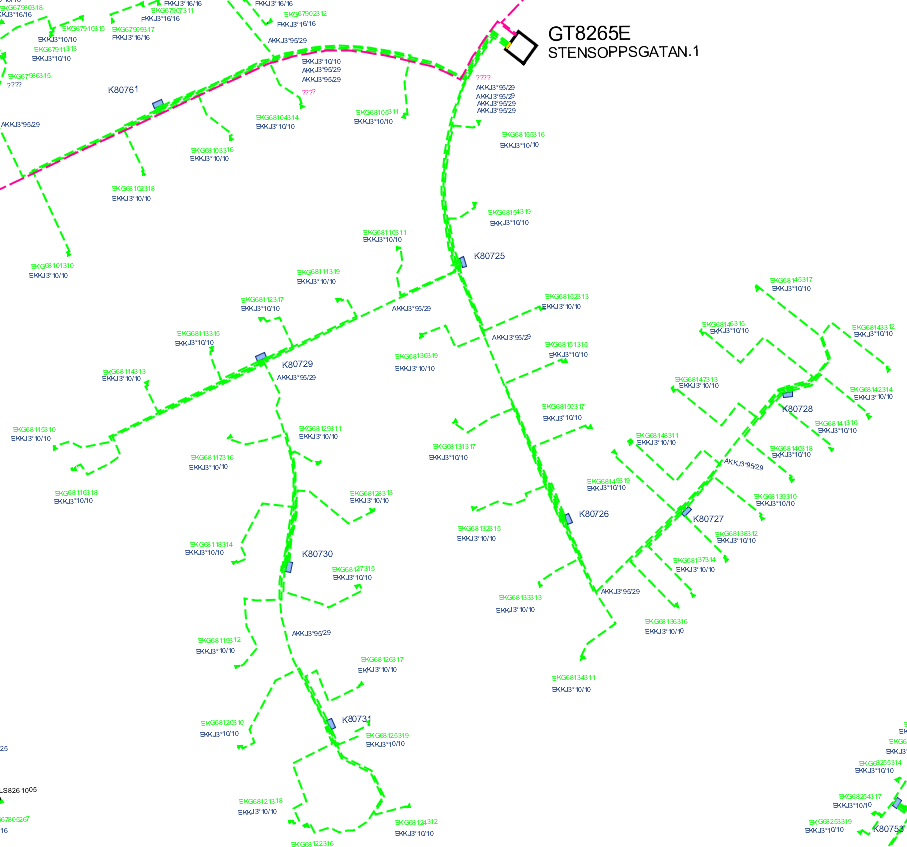
1.Fill in the necessary information in the Trace menu.
2.Press Trace. The traced network lights up.
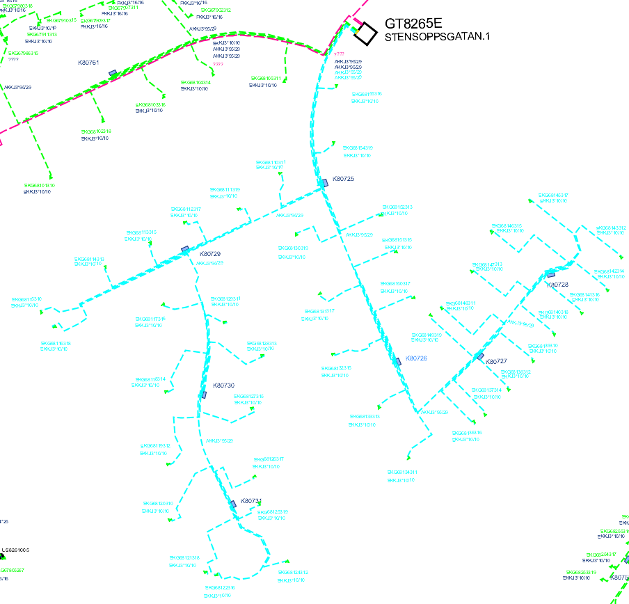
3.If there are planned loads in the traced network, a dialog with these will be opened and you will be asked if they are to participate in the calculation. The right-click function can be used for positioning in the map. If the planned loads are the right ones, press OK.
When the trace is done, the dialog for network calculations opens where the parameters about the calculation should be entered or the dialog for the auto schema, where settings for the schema can be modified.