Measurement point (otype - 721100) is the main object in dpPower to manage SCADA analog values and historical measurement values for stations. The measurement point is linked to the network topology.
|
In addition to meters in customer facilities, the Meter Alarm module can also manage stationary meters. When a fault is detected by such a meter, it is automatically registered as an event in dpPower, linked to a metering point. |
The measurement point is not a physical device, but a data object that often combines values from different physical meters, such as current and voltage transformers, to display readings and events.
Place Measurement point
|
Measurement points can only be placed in the schematic view. view. |
When the measurement point is placed, it is linked to the network. The measurement point can be linked to the network in two ways:
•On switching devices (such as switches, fuses or disconnecting devices) - used to measure current and power.
•On busbars - used to measure voltage.
See section Place objects and components for a general description of how to place objects in the graphical view.
Link to a switching device
In this example, a new measurement point is linked to the secondary side of a station.
1.Select object to link to - Select a switching device, for example a Circuit breaker, on the secondary side.
2.Select connected object to find terminal - Since the measurement is on the secondary side of the transformer, select the Transformer bay.
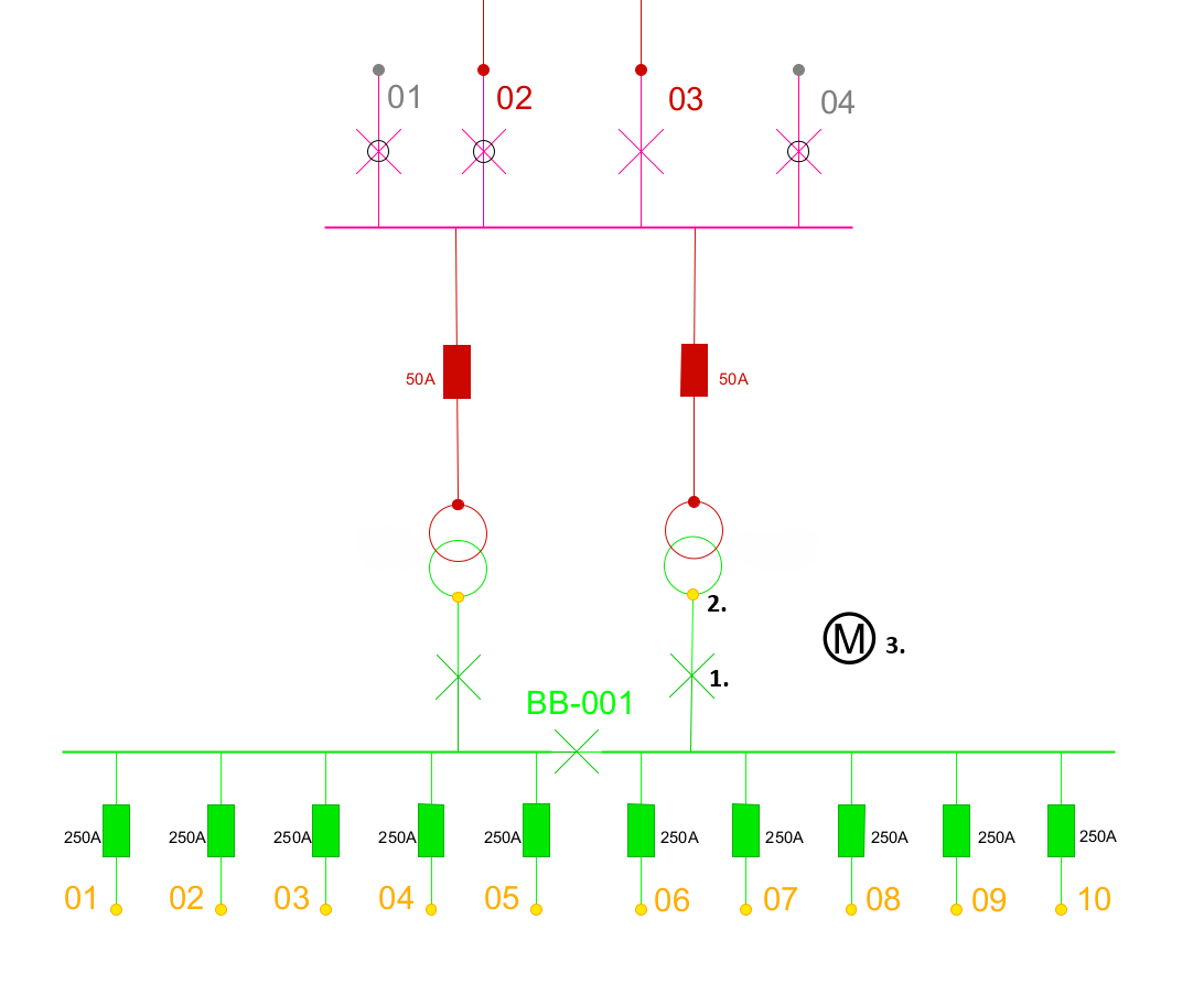
1. A Circuit breaker selected as object to link to.
2. A Transformer bay selected to find terminal.
3. The symbol for Measurement point placed.
Link to busbar
If voltage measurement is to be done via a busbar, simply select the desired busbar when placing the measurement point.
Add SCADA measurement
SCADA measurement definitions are added as the Measurement (ctype - 2090) component on the measurement point object.
1.In the measurement point attribute form, select the Measurement tab to see all components.
2.In the Measurements section, press Add to create a new measurement.
Three fields are mandatory for integration:
•Measurement ID - Enter the SCADA_ID or external SCADA ID.
•Measurement source - Select the data source, in this case, SCADA.
•Measurement type - Select the unit of measurement.
Add a station meter to the measuring point
A station meter can be represented by one of the following objects:
•Meter (billing meter) - otype 20002
•Network meter - otype 729000
The Network meter object allows you to specify the measurement location within a station and enables the storage of measurement data from the station, such as transformer power or energy readings.
Create a network meter
1.Right-click on the Measurement point object.
2.Select Create new meter > Network meter.
Mandatory attributes for integration:
•Alternative ID - The Meter site ID or system meter ID. This ID should not be changed, because:
oIntegration and import are based on this ID.
odpPower stores history based on this ID, if ID is changed, history is lost.
•Measurement source - Select from the code list:
oMETER_HOUR - Data from the hourly measurement module in dpPower Analyzer. Can be imported as quarter values (15 min) or hourly values (1 h) from four quadrant meters (4Q). Data imported as quarter values are automatically converted to hourly values.
oSCADA - Data from SCADA integration.
Optional but recommended attribute:
•ID - Meter ID according to the grid owner, for example serial number.
Once the network meter has been created and connected to the measurement point, it is displayed in the measurement point's attribute form, tab Measurement, section Meters.
Display measurement values in the schema
Measurement value, text is a component placed in the schema to display measurement data from a measurement point or meter.
Two ways to add measurement text:
Alternative 1 - After the measurement point is placed:
1.Right-click on the Measurement point object.
2.Select Object > Place component for object > Measurement value text, schema.
3.Place the component where you want to display the measurement value. The text N/A is shown as placeholder until measurement values are retrieved.
Alternative 2 - Directly at the placement of the measurement point:
1.In the Placement field, select Link and create text. Only the measurement text is placed in the schema, not the measurement point symbol. The text N/A is shown as placeholder until measurement values are retrieved.
|
The Link and create text option requires a special feature. Contact Digpro for installation. |
Update values in real time
|
This function requires a special feature. Contact Digpro for installation. This function also requires the LIVE_MEASUREMENT_READ role. |
After you have placed a Measurement point with the Link and create text placement option, you need to enable the real-time measurements function to see measurement values.
1.In the menu bar, select Analyzer > Analyzer real-time > Check Show/Hide real-time measurements.
When real-time measurements are enabled and displayed in the schedule, you can get additional information:
•Hover over a real-time value to see the time of the last measurement and a trend line showing how the value has changed over time.
•Right-click on a real-time value and select Analyzer > Display measured values to display historical data. You can select which time interval to view.
•Outdated values are marked with a strikethrough, indicating that the information is no longer current.
View the measurement point values as a chart
1.Right-click a measurement point in the schema and select Analyzer > Display measured values.
2.Enter the Start date and End date. If the date fields are left blank, all dates are used.
3.Check the box for Measured type.
4.Press OK. A window opens showing charts with measurement values over time.
Options in the chart view
When the chart is displayed, several options are available:
•Adjust the appearance of the chart via the Settings menu, such as line type, titles or other graphical properties.
•Export the chart as a PDF or to a spreadsheet program via the File menu.
•Press the Display value ![]() icon and select a point in the chart to see the exact value at that timestamp.
icon and select a point in the chart to see the exact value at that timestamp.
•Press the Display duration chart ![]() icon to see a graph showing how long a particular measurement has occurred.
icon to see a graph showing how long a particular measurement has occurred.