Regulation points are created in the map, not in the schematics. Regulation points can be created in the voltage levels 0.400 kV, 0.500 kV and 1 kV.
|
For detailed description of how to place objects and components, see section Place objects and components. |
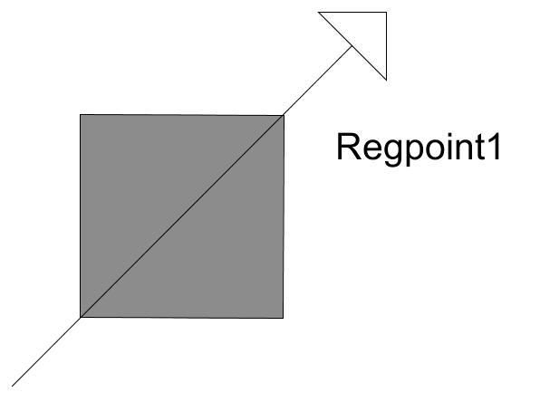
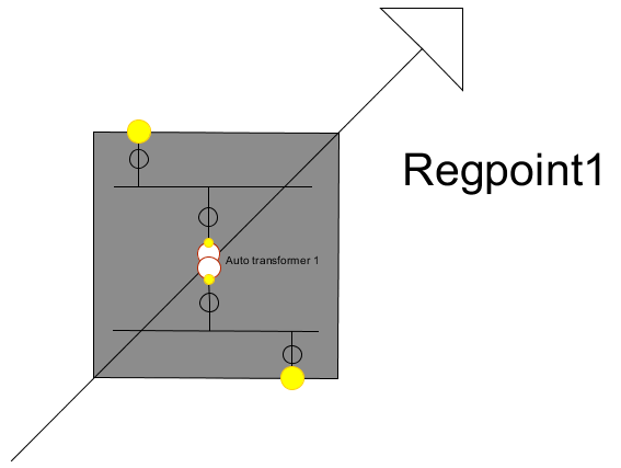
A regulation point created in the voltage level 0.400 kV can look like this:

The following objects have been placed in the image above:
•1 pc Regulation point
•2 pc Substation Bus bar in regulating point
•2 pc Disconnector in regulating point (From a bus bar, create bay)
•2 pc Disconnector in regulating point with (From a bus bar, create transformer bay)
•1 pc Auto transformer
1.Open the sidebar ![]() .
.
2.Select the Place object tab.
3.Select 0.400 kV > Stations > Regulating point, 0.400 kV.
4.Press the Place object button.
5.Fill in relevant information in the attribute form that opens and press the OK button.
6.Place the regulating point in the map.
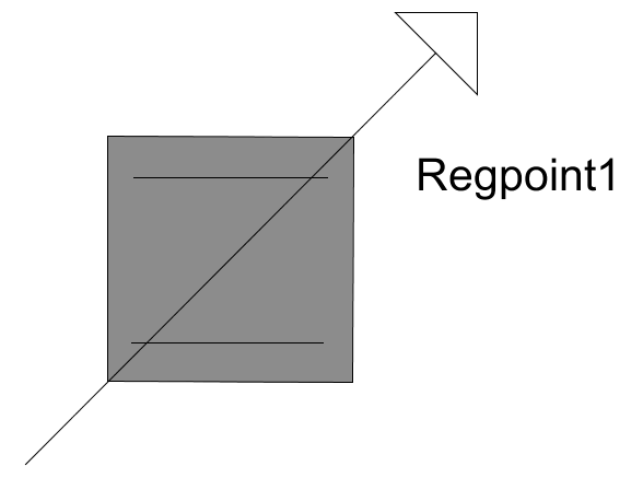
7.In the sidebar, select 0.400 kV > Miscellaneous in station > Substation Busbar in regulating point, 0.400 kV.
8.Press the Place object button.
9.Fill in relevant information in the attribute form that opens and press the OK button.
10.Select the regulating point as parent and place the busbar in the map.
11.Place another busbar in the same way.
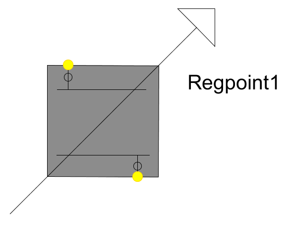
12.In the sidebar, select 0.400 kV > Miscellaneous in station > Disconnector in regulating point, 0.400 kV.
13.Select placement From a bus bar, create bay.
14.Press the Place object button.
15.Fill in relevant information in the attribute form that opens and press the OK button.
16.Select the top busbar as the object to connect from and place the disconnector in the map by dragging the disconnector upwards.
17.Place another disconnector in the same way, but connected to the lower busbar and drag the disconnector downwards.
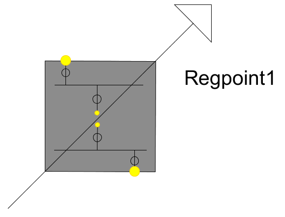
18.In the sidebar, select 0.400 kV > Miscellaneous in station > Disconnector in regulating point, 0.400 kV.
19.Select placement From a bus bar, create transformer bay.
20.Press the Place object button.
21.Fill in relevant information in the attribute form that opens and press the OK button.
22.Select the top busbar as the object to connect from and place the disconnector in the map by dragging the disconnector downwards.
23.Place another disconnector in the same way, but connected to the lower busbar and drag the disconnector upwards, towards the previously placed disconnector.
24.In the sidebar, select Transformers > Auto transformer.
25.Press the Place object button.
26.Fill in relevant information in the attribute form that opens and press the OK button.
27.Place the transformer between the most recently placed disconnectors.
28.Fill in more information for the auto transformer by:
a.Right-click on the transformer ID and select Show/change attributes.
b.Select the Network calculation data tab and fill in the desired fields.
c.Press the OK button.
29.Fill in more information for the incoming winding by:
a.Right-click on the incoming winding and select Show/change attributes.
b.Select the Tap changer data tab and press the Add button.
c.Fill in the desired fields and press OK.
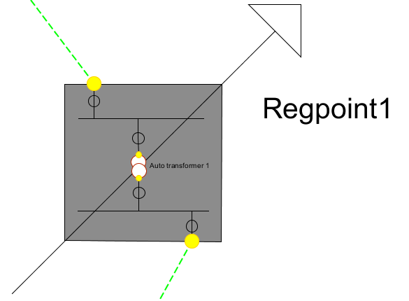
30.Connect lines to the bays.
31.Create Regulating point template by, in the menu bar, select Tools > Templates > Regulating point template > Map > Define.
32.In the menu bar, select Place > Regulating point template, and select the one you have created.