Alarm boundaries for the printouts of the reports are defined here:
Edit and add alarm parameters
Edit boundaries by selecting a row and press Edit.
The dialog Editor for Alarm limits is opened.
You can also add a new alarm by pressing the button Add. An empty form will then be open.
Note! |
In order for the alarms to be accessible for all the parameter sets, either the same procedure must be done for each set of parameters, or as an alternative, a SQL-script must be executed. Contact the supplier for more information. |
Own alarms can be replaced with a standard template from the system supplier when upgrades are done. |
The two rows Unique id and Parameter id are entered automatically when pressing OK and is therefore not editable.
Enter an optional character for the Alarm Type.
Then determine the voltage level that the alarm should apply by entering upper and lower voltage and Operator UE and US.
Select an alarm value, eg A or B. A alarm is more serious than B alarm.
Select what kind of values to measure by specifying the Measurement Type. This affects which device is used for values A and B, for example, voltage drops are measured in percentage, but Energy read is measured in kwH.
If the alarm should apply to a certain interval within the measurement type (eg voltage drop of 3% - 5%), then the interval is set to give alarms with values A and B, and Operator A and B.
If the alarm should apply to a certain relationship between two types of measurement values (eg calculated voltage setting and maximum allowable voltage), then the measurement type 2 is selected under Measure Type 2 and how to compare it is specified with Operator A.
Alarm type / TYPE |
Internal ID that becomes "title" in the reports. May be an optional character. Consistency for multiple alarm limits against the same result term. |
Alarm value / ALARM |
These values are printed in the lists.. |
Unique ID / ROW_ID |
Automatically set when alarm is created. |
Parameter id / ID |
Automatically set when alarm is created. |
Fields for voltage level in the network that the alarm should be applied to
Upper voltage / UE |
Upper system voltage limit, kV. |
Operator UE / OPUE |
Alarm when system voltage is: not equal to / less than / less or equal to / greater than / greater or equal to the upper system voltage limit. |
Lower voltage / US |
Lower system voltage limit, kV. |
Operator US / OPUS |
Alarm when system voltage is: not equal to / less than / less or equal to / greater than / greater or equal to the lower system voltage limit. |
Fields that define the alarm interval
Value B / VALUB |
The limit for the value. The unit depends on what is chosen as the measurement type. |
Operator B / OPB |
Value B shall be: not equal to / less than / less or equal to / greater than / greater or equal to. |
And/or / BOOL |
Value B shall be [Operator B] AND / OR Value A shall be [Operator A]. AND = And. No value = Or. |
Value A / VALUA |
The limit for the value. The unit depends on what is chosen as the measurement type. |
Operator A / OPA |
Value A shall be: not equal to / less than / less or equal to / greater than / greater or equal to. Alternate: Measurement type shall be: not equal to / less than / less or equal to / greater than / greater or equal to measurement type 2. |
Fields for selecting what to measure
Measurement type / ALARMID |
What kind of value that should be measured |
Measurement type 2 / ALARMID2 |
Another type of value that shall be compared to the Measurement Type |
Example 1:
Register an alarm that should for a LV network give an “S”-alarm for all energy values read and have values between 25000 and 50000 kWh.
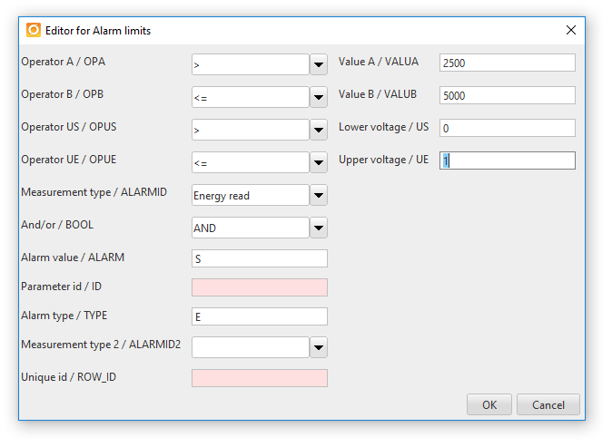
•Here the alarm type is "E".
•The voltage should be between 0 and 1 kV (low voltage).
•The alarm value is "S".
•The B value should be less than or equal to 50,000 kwH and the A value should be greater than 25,000 kwH.
•The result term to be watched is "Energy read".
Example 2:
Test two saved values against each other.
Register an alarm when calculated voltage rigidity is greater than the maximum allowed voltage setting earth fault.
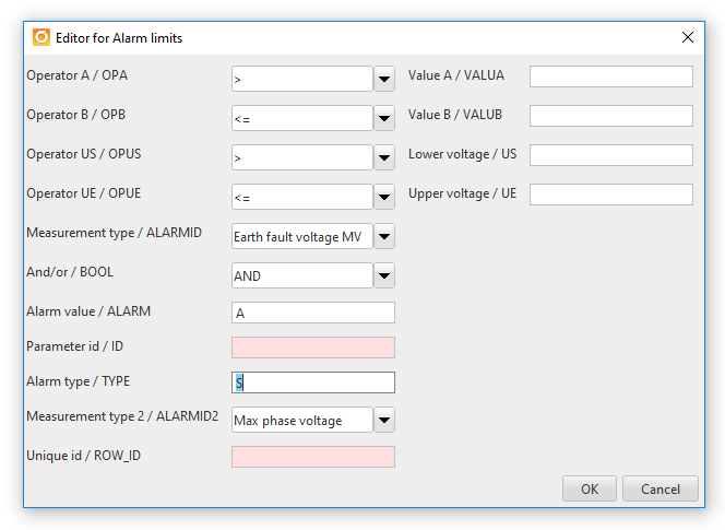
•Here the alarm type is "S".
•The alarm value is "A".
•The earth fault voltage setting (Measurement Type) shall be greater than the maximum phase voltage set (Measurement Type 2).
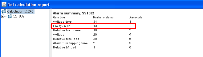
View the alarm report after a network calculation
Alarm composition
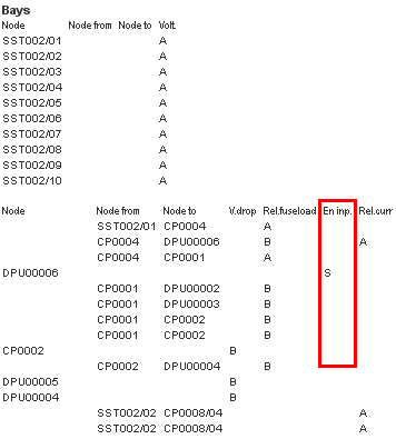
Alarm in report
