1 Parameter Comment
Description:
Comments for this set of calculation parameters.
2 Loss Constant
The Loss constant is included in the formula for calculating energy losses. Varies between 1.2 – 1.7. Standard value = 1.4.
3 Network Frequency
Net frequency expressed in Hertz.
4 Load Flow Calculation Criteria
Max iterations:
Maximum allowed iterations the load flow program may loop through to converge before halted. If Max iterations are set> 999 (i.e 1000), a special overload check will be performed which presents overloaded lines and transformers in the calculation log. That is, all that are loaded over 100%.
Convergence Criteria
The p.u.voltage drop delta between two iterations when the program will stop trying to improve voltage accuracy. Normally 0.01 - 0.001.
5 Network reduction
Network reduction is used for reducing two-line joints during network calculations. This means that lines with joints are replaced with electrically equivalent section. The control properties for the resultant section are taken from the “weakest” line. The main purpose of network reduction is to simplify analysis of the networks with parallel lines or multiple feeding points.
Network reduction LV
If checked, the reduction will be done for low voltage networks.
Network reduction HV
If checked, the reduction will be done for high voltage networks.
Example:
Two parallel cables with several joints between two cable pillars.
With a network reduction an error analysis of parallel cables can be done.
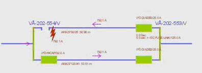
And the same is also valid for two parallel cables from a substation.
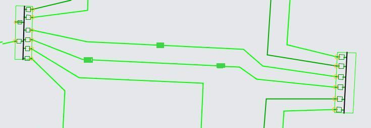
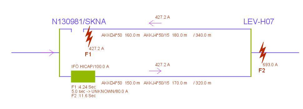
Example network reduction:
In the network as seen below, a calculation is done based on the activated reduction and with request of parallel schematics.
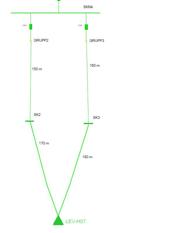
Automatically generated parallel scheme
--------------------------------------------------------------------------------------------
Substn Bay ID Node from Node to Length m Conductor Curent A
N130981 Group2/Group3 N130981/BUSB LEV-H07 160.0 B_AKKD4*50 35.23
N130981 Group2/Group3 BB3 DEL-H07 180.0 R_AKKJ4*50/15 35.23
N130981 Group2/Group3 N130981/BUSB DEL-H07 150.0 B_AKKD4*50 37.43
N130981 Group2/Group3 BB2 DEL-H07 170.0 R_AKKJ4*50/15 37.43
--------------------------------------------------------------------------------------------
Explanation of the presentation of network parts that are included in the network reduction
All the sections that are included in the reduction are presented in the result report. The section that represents the combined section has a "B_" prefix on the line type description. That section contains all parts from the merged sections. Node points End and Start are printed together with the points in each end of the merged sections. The length comes from the “original section” that has been chosen to represent the merged sections. The "B_" cable receives the merged impedances from all the sections parts but the control properties are coming from the “original section”. If there are fuses at the start and/or end section they will be presented in the "B_" section.
The reduced sections will receive an "R_" prefix in the line type description. They are only presented as information and the calculation results presented for these sections are coming from the resulting "B_" section.
If voltages in a node point result are presented in the report the result will only be written on one of the rows. It can be on either a B_-row or a R_-row.
Example for a point LEV-H07
--------------------------------------------------------------------------------------------
Substn Bay ID Node from Node to Length m Volt. V Volt.drop
N130981 Group2/Group3 N130981/BUSB LEV-H07 160.0
N130981 Group2/Group3 SK3 LEV-H07 180.0 246.0 2.87
N130981 Group2/Group3 N130981/BUSB LEV-H07 150.0
N130981 Group2/Group3 BB2 LEV-H07 170.0
--------------------------------------------------------------------------------------------
6 Fault Analysis
Resistance inc. calc. LV.
If checked, the calculation program will consider any available resistance increasing factors in line type codelist (ELCBLTYPE_CL). See appendix: Earth faults using increased resistance due to warm conductors