With the drawing attributes administration tool in dpPower, a system administrator can change the appearance of the map products used in the organization. For example, it is possible to edit the default settings for how lines and texts appear regarding the color, size, scale interval etc. It is also possible to change the way objects appear in the map view regarding their states and how they should be visualized. The drawing attributes administration tool offers many ways to create a standard and homogeneous map style, recognized by all that works with the application.
The drawing attribute tool consists of two editing tools, one for normal drawing attributes and one for alternative drawing attributes. Select the Drawing attributes or Alternative drawing attributes tab in the upper left corner of the window.
|
To change drawing attributes, the EDITATTRIBUTES role is required. |
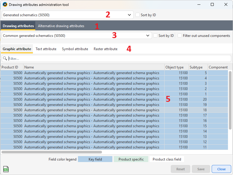
The interface of the drawing attributes tool:
(1) The main tabs provide access to the normal and alternative drawing attribute tools respectively.
(2) and (3) Drop-down lists where you select the product or product class containing the components to be edited.
(4) Tabs with components sorted by component type.
(5) Attribute fields where the drawing attributes are edited.
Edit drawing attributes
1.Select Administration > Map product > Drawing attributes administration tool.
2.In the Drawing attributes tab, select product in the top drop-down list.
|
You can also configure drawing attributes at the product class level by selecting All products (-1000000) in the product list. This will make the settings apply to all products that use the selected product class. This function is only available for custom product classes and cannot be used for standard products included in the system. |
3.Select the product class in the next drop-down list. The product class member components are filtered and sorted by component type in the Graphic attribute, Text attribute, Symbol attribute and Raster attribute tabs.
4.Select the tab that contains the component type you want to edit.
|
If you only want to see the components that are actually used in the product class, meaning, the component types that are placed in the graphical view, check the Filter out unused components checkbox on the right side of the tool window. |
5.To edit a drawing attribute value, double-click in an attribute field, enter or select a new value and press Enter. When you change a drawing attribute, the result is updated directly in the graphical view. This allows you to test different settings until you find a drawing style that you want to save.
|
Light blue fields, known as Key fields, cannot be edited. |
6.To save the new settings, press Save. To reset unsaved drawing attributes to previous values, press Reset.
|
You do not need to change each component one by one. To copy a value to multiple components: 1.Right-click the desired value and select Copy, or use the keyboard shortcut Ctrl-C. 2.Select the components to be changed using the Ctrl or Shift key. 3.Right-click and select Paste, or use the keyboard shortcut Ctrl-V. |
|
To reset drawing attribute values set for a product (light green fields): •Select the desired cell, right-click, and select Set default attribute to selected rows to reset all values for the component. •Select Set default attribute to cell to reset only the selected value. |
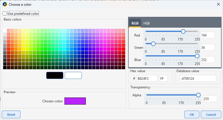
Edit a color attribute
1.Double-click in a color attribute field. A dialog opens.
2.Select a color from the palette under Basic colors.
3.Customize the RGB values and transparency in the RGB and Transparency tabs.
4.If you want to use the original color of the component, check the Use predefined color checkbox.
5.To save the new settings, press OK.
Alternative drawing attributes
Alternative drawing attributes allow you to control how objects are displayed on the map, for example based on their states or other attributes. These drawing attributes are used instead of the regular drawing attributes when conditions are met. This is a powerful way to customize the visualization, but should be used with caution as it can affect performance.
Alternative drawing attributes are often used to show objects in special conditions, such as downed wires, with a different style such as a dotted line or different color. You can define these attributes with different levels of detail - from general rules for an object type to specific combinations of object type, subtype and component. In some cases, drawing attributes can also be set directly on individual components in the database, which always takes precedence over general settings.
You can add alternative drawing attributes directly in the application or have them loaded via scripts by Digpro.
Add alternative drawing attributes
1.Select Administration > Map product > Drawing attributes administration tool.
2.In the Alternative drawing attributes tab, select the product in the top drop-down list.
3.Select the type of attributes you want to add using the different tabs and press Add. A dialog opens.
4.Fill in the information that will apply to the new drawing attribute:
oThe Object type, Subtype and/or Component type determine which objects the attribute applies to. If you enter values for all three, it applies to that particular combination.
oState is used to control the visualization based on the life cycle of objects. When specifying the state, it is useful to specify the Schema owner as well, as different owners may have different meanings for a given state number.
oDisplay flag can be used for more advanced control using code listed values.
oDescription is an optional but recommended field to document the purpose of the attribute.
5.Press Save to create the row in the database.
6.Edit the drawing attribute properties, such as color, line style, symbol font, and press Save.
|
You cannot change the Product ID field. The other fields are edited by double-clicking and entering a new value. |
Draw order
Draw order values control the order in which maps and objects are displayed in the z-axis of the map. Objects with higher drawing order values are drawn on top of those with lower values. By using drawing order, you can control layer order and avoid hiding important objects.
Recommended drawing order values
•Assign background maps lower drawing order values than map objects.
•Assign higher values to smaller objects than to larger ones, to avoid covering them.
•Assign polygons lower values than symbols, symbols lower than lines and lines lower than text.
We also recommend:
•That imported maps and data be assigned negative drawing order values.
•Assigning positive drawing order values to map objects.
•that drawing order values for the component types of map objects are created by adding them to the drawing order values of the map objects.
See examples in the tables below.
Background maps |
Draw order value |
|---|---|
World map |
-200,000 to -100,000 |
Map of Europe |
-200,000 till -100,000 |
Map of Sweden |
-50,000 till -25,000 |
City map |
-25,000 till -2,000 |
Primary map |
-2,000 till -1 |
Network information |
Draw order value |
|---|---|
Pipe/shaft |
-200,000 till -100,000 |
El/opto |
-200,000 till -100,000 |
Information object |
-50,000 till -25,000 |
Component type |
Draw order value |
|---|---|
Polygon |
+10 |
Line |
+20 |
Symbol |
+30 |
Text |
+40 |
Change drawing attributes on individual components
The Show/change drawing attributes option opens a dialog box that allows you to temporarily change the appearance of the component in the map. Grayed out attributes cannot be edited.
For raster images, such as orthophotos and overview maps, you can only adjust the Draw order attribute, meaning, the level in the layer sequence in which the image should be located. The order is in ascending numerical order, where "0" (sometimes also negative values) is at the bottom/back of the layer sequence.
Example: Image A is above Image B, if A has Z value "5" and B has "0".
1.In the sidebar tab Map, select one or more graphical components.
2.Right-click and select Show/change drawing attributes.
3.Adjust selectable drawing attributes and press Apply to apply the changes to the map.
|
If changes to drawing attributes do not take effect, select Settings > Preferences > Colors tab to control how changed and locked components are displayed. These settings take priority over the temporary changes you make to the map tree. |
See also:
For more information about drawing attributes and the tools and functions used to customize the appearance of map data, see section More about drawing attributes.