Creates an additional vertex (break point) to a component.
|
You can lock the movement when placing or moving a vertex: •Press N to lock the movement to north-south direction. Press N again to unlock the direction. •Press E to lock the movement to east-west direction. Press E again to unlock the direction. If both N and E are enabled, movement is locked in all directions. When you add a vertex to a line segment, you can press O to enable orthogonal mode. The vertex will then be placed so that the two new line segments form a right angle. Press O again to disable orthogonal mode. |

|
If the wrong component, segment, or vertex is selected, you can right-click to select the next possible match. |
|
In the schematic view, dynamic guides may appear when you place or move a vertex near an extended horizontal or vertical line from another vertex. When the mouse pointer is near an extended horizontal or vertical line toward a vertex, a dotted guide line appears between the mouse pointer and the vertex. Press the spacebar to turn off the guide lines. Press the spacebar again to enable them. |
|
If you snap the new vertex to a vertex with a Z-value, for example from a reference object, the Z-value is automatically copied to the new vertex. |

Add a vertex to a line segment
1.Select Edit > Component > Add vertex (A) or press  in the toolbar.
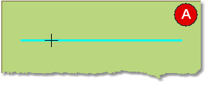
2.Select the component you wish to add a vertex to. The component is highlighted, illustration (A).
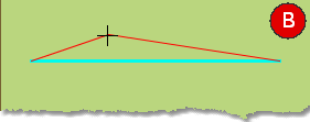
3.Select position for placing a new vertex. A preview of the result is shown in red, illustration (B).
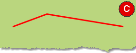
4.Left-click to add the vertex. A new vertex for a component has been created, illustration (C).
Add a vertex after start or stop point
1.Select Edit > Component > Add vertex (A) or press in the toolbar.
2.Left-click the component's start or end point.
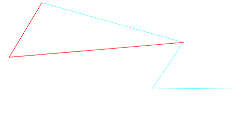
3.Place one or several new vertices (points). A preview of the result is shown in red.
More information
See also section: