The Show cable path function is used to display a schematic representation of a cables path through the network.
Cable paths are used, among other things, to trace a cable through the network, analyze connections between nodes, and get an overview of the cable’s route.
Show cable path in the active view, in another view, or in a new window.
Show cable path
1.Right-click the cable on the map.
2.Select Show cable path.
3.Select where the cable path should be shown:
oActive view
oAnother view
oNew window
Show the cable path as a schematic representation in the selected view.
Show compact cable path
The Show compact cable path function works the same way as Show cable path, but does not display event nodes.
The compact view provides a clearer overview of the cable route and is primarily used when the focus is on the cables path through the network.
Interpreting the cable path diagram
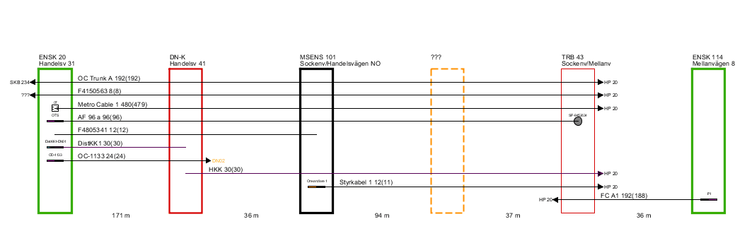
When a cable path is shown, it is presented as a schematic diagram of the selected route.
The start node is shown on the far left and the end node on the far right. Between these, all intermediate nodes and the path lengths connecting them are displayed.
Cables that run entirely or partially along the path are shown as lines in the diagram. For each cable, a label is displayed with:
•cable ID,
•number of fibers or Thread/carriers,
•number of available fibers or Thread/carriers (in parentheses).
If a cable is connected to equipment in any of the nodes, this is also shown in the diagram.
If a cable leaves the displayed route, this is indicated by an arrow and the ID of the node toward which the cable continues. Note that this is not always the same node where the cable ultimately terminates.
Press F5 to close the show cable path.
Show pipe paths
The Show pipe paths function works the same way as Show cable path but displays pipes and ducts instead of cables.
The diagram can be used as a planning and documentation aid for cable routing through pipe and conduit systems.
Examples of use cases:
•identifying suitable pipes and ducts between two nodes,
•planning route paths for new cables,
•getting an overview of the contents of a multiduct.
When working with route paths, the diagram can be used as a guide in conjunction with the Put cable/pipe in route/pipe command, where the cable is gradually extended through the available pipes and conduits.
If the start and end nodes are placed at opposite ends of a multiduct, the diagram provides an overview of all conduits in the multiduct, including how the conduits are viewed from the end node’s perspective.