Distribution point connection diagram is available as an auto-generated view. The view is also active, which means that it is possible to right-click and open the objects from the view.
Generate distribution point connection diagram
1.Select Reports > Distribution point connection diagram.
2.Then select starting object, e.g. distribution point, cable or rack.
Example
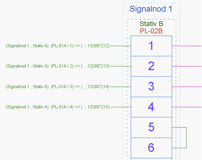
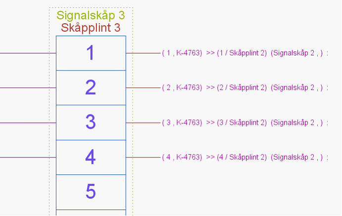
Example of generated distribution point connection diagram.
|
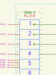
The image shows the node/cabinet ID at the top, then the rack and terminal ID. The green lines show cross-connections made within the distribution point (examples 5 to 6) or between distribution points (the green ones on the left). The red ones show connection to the distribution point in another node/cabinet. The text displayed for the cross-connection shows the node/cabinet id, rack id, distribution point id and unique id of the cross-connection wire. |
|
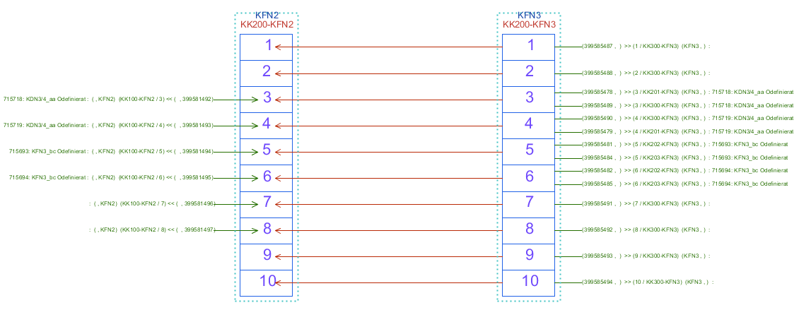
The image corresponds to the second node/cabinet of the distribution point search and contains the same information as in the text above. The difference is that the red lines, the wires, indicate the wire number, cable ID, terminal/terminal row ID and node/cabinet ID. |
|
When selecting and right-clicking on an object in the distribution point connection diagram, which is active, it is possible to perform all the functions that can be performed on the object in the diagram. |
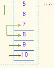
When using the right/left function when connecting wires to distribution points, it is shown on which side the connection is made using arrows, see example below.
|
|
Above on the left it is shown that the cross-connection is connected on the left side of terminal 1-3 and the right picture that the internal cross-connection between terminals 7 - 8 and 9-10 is made on the right side and between terminal 5-6 on the left side. |
|