The option Operator preferences opens a window with two tabs: My preferences and Shared preferences.
The My preferences tab
The tab contains the following sections:
•Show symbols in map - Select which symbols to display on the map when Operator is shown.
•Dynamic coloring - Select to colorize the network based on whether it is energized and/or grounded.
•Other - Decide how you want the south and east panels to open:
oDocked in the main window
oTogether in a separate window
oSplit into two separate windows
Dynamic coloring
To give a user access to dynamic coloring without other Operator rights, the administrator can assign only the OPERATOR_DYNAMIC_COLOR role. With this role, the user can activate the function from the toolbar and adjust settings under Operator > Operator preferences but does not have access to other operator functions. |
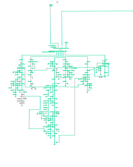
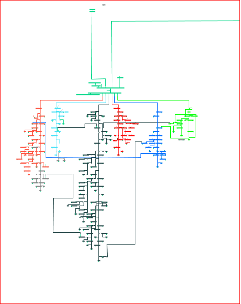
Dynamic coloring provides a visual overview of the current status of the network, making it easy to identify areas that are energized, multi-fed, or de-energized directly in the map or schematic. In the event of a fault or outage in the network, dynamic coloring can be used to quickly identify which parts of the network have lost power (displayed in gray) and which parts remain energized.
The coloring is controlled by the topology analyzer, which determines which objects are fed and whether they are multi-fed. The default behavior is as follows:
•Basic coloring - Objects are color-coded based on voltage levels.
By default the voltage levels 6 kV, 10 kV and 20 kV are configured, these default values can be configured as desired, contact Digpro support. |
•Multi-feed objects - If an object can be traced to more than one active feeding bay, it will be marked as multi-fed and displayed in bold yellow color in the default configuration.
Color and line style can be configured as desired, contact Digpro support. |
The topology analyzer considers an object to be energized if it can be traced to an active bay. For a bay to be considered active, the following applies:
•The bay must be of type Substation bay, otype=707000. Other bay types are ignored.
•There must be a traceable path from the bay to a feeding busbar without open switching devices in between.
•The bay must have a voltage level (subtype) that is in the configured accepted subtypes list.
•The bay must have a lower voltage level than the station it belongs to.
Example: A 10 kV bay in a 20 kV station is active, but a 20 kV bay in the same station is not. Exception - If the bay belongs to a substation switchstation, otyp=702006, it can have the same voltage level as the station. |
Feeding bay attribute: •Force feeding makes the bay active by default. •Force non-feeding makes the bay inactive by default. |
It is possible to configure a setting to ensure that only stations with voltage transformation have active bays, switch stations will then not have active bays. If this configuration is desired, please contact Digpro support. |
If the function is switched on, the de-energized mesh is displayed in grey. The function can also be started from the toolbar with the button  . If dynamic coloring is not updated correctly after restarting the topology analyzer or after stopping and starting Operator, the coloring may need to be reset manually. This is done by turning the function off and on again.
The Show Path to Source function can be used together with dynamic coloring to identify voltage sources and their path in the network. This combination is useful, for example, to understand and analyze multi-fed networks. To view the voltage source and the path to it, see section Show path to source.
The alternative Power and earthing can look like this:

The alternative Power, earthing and feeding bays can look like this:

The Shared preferences tab
The tab contains the following subtabs:
•Auto-publish - Publish outages in the outage map automatically.
•External announcements - Activate all automatic and semi- automatic announcements. Set the desired options for the automatic announcements.
For example, you can send automatic announcements when an outage has been automatically resolved by selecting Yes in the Outage is restored automatically field under the heading Outage ends > Automatic in case of. This option can be used in conjunction with the automatic restoration of meter alarm outages function. Once the outage is resolved, automatic announcements are sent to customers via SMS and/or email, without any further action by field crews.
•Automatic announcement meter alarm - Send announcements automatically for meter alarms that have occurred due to customer faults.
•Resource announcements - Add recipients and select preferences for sending.
•Organizer - Automatically create tasks in Organizer based on templates when an operation outage has been added. The organizer task templates need to have underlying activities with the label OPERATOR_VISIBLE and/or OWM_LAYOUT_OPERATOR. The task creation can be triggered by both SCADA events and meter alarms as well as fault reports from customers. The functionality enables all operation outages to be handled according to a predefined methodology and it is primarily intended to be used in combination with dpWebmap - Operator. The function give dpWebmap - Operator users access to outage information in their phone when an outage occurs and can then take suitable action.
•Operating orders - Add resources under For action and For information. These resources are then automatically added to the flyleaf of each new operating order.
•Switch order - Activate a warning that warns the user if the connection state of the switches differs between the start and the end of an outage. The warning reduces the risk of leaving the network in a state which differs from normal feeding after an outage has been fixed.
•Meter integration - Automatically create outages from meter alarms.