DXF (Drawing eXchange Format) and DWG (Drawing) are vector-based file formats from AutoCAD. DWG is the original binary format used in AutoCAD, while DXF is a text-based ASCII variant developed to facilitate the exchange of drawing data between different programs. Both file types can be used as a basis in Digpro applications.
Files in DXF/DWG format are often used as background data to support documentation and planning. It is also possible to import DXF data as object types other than background data. It is also possible to add the original file name to attributes even if it is network objects to be imported in a DXF import.
|
Importing DXF/DWG files requires a mapping file. A mapping file is a file containing information on how to translate data in a DXF/DWG file to data in dpPower. |
Generate DXF/DWG mapping file
A mapping file is a text file containing instructions on how to interpret the data in the DXF or DWG file and map it to components in dpPower. There are two ways to create a mapping file:
•You can use a built-in tool in the application that helps you create a draft mapping file. The tool reads the content of the DXF or DWG file and automatically generates key fields for the elements to be mapped.
•Alternatively, you can create the entire mapping file manually from scratch in a plain text editor.
Structure of a mapping file
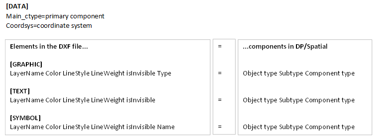
The mapping file contains four sections corresponding to component types in dpSpatial:
•[DATA] - defines primary component and possibly coordinate system.
•[GRAPHIC] - mapping of graphical elements such as lines and points.
•[TEXT] - mapping of text elements.
•[SYMBOL] - mapping of symbol elements.
|
All fields and the equal sign are separated by a space, except in the DATA section where no spaces should be used. |
DATA section
•Is mandatory and contains information about the primary component, meaning, which data component ID the DXF file gets in the database when it is imported.
•If the DXF file uses a different coordinate system than the project in dpSpatial, this is specified in the coordsys attribute.
•When importing object types other than background data, no primary component is specified here - the program identifies the correct primary components itself, which slows down the import.
GRAPHIC, TEXT and SYMBOL sections
Each row in these sections consists of several key fields on the left and a mapping on the right:
The key fields are:
1.Layer Name (LayerName)
2.Color (Color)
3.Line style (LineStyle)
4.Line thickness (LineWeight)
5.Is invisible (isInvisible)
6.Type for graphic elements or Name for symbol elements
You can also specify State and Display_flag after the component type:
•If you omit these values, the default 0 0 is used.
•If you specify them, you must specify both values (State and Display_flag).
Wildcards (*) can be used to replace optional fields.
The right side after the equal sign indicates how the keys should be mapped to a component in dpSpatial:
•Object Type
•Subtype
•Component type
A component, together with its primary component, forms an object in dpSpatial.
Example:
[GRAPHIC]
2GOSLAG_K * * 1 false line = 312000 27 356320
Here, the 2GOSLAG_K layer is mapped to:
•Object type 312000 (Primary map - graphic)
•Subtype 27 (Property border,forest,mountain,field,marsh, modifiable, active)
•Component type 356320 (Primary map graphic)
In this example, color and line format are replaced by wildcards (*), line thickness is set to 1, and the element is visible (false = not invisible).
Simple mapping file
The easiest way to create a mapping file is to enter only the layer name and replace other fields with wildcards. It is even possible to replace all fields with wildcards, which means that all elements in the section are mapped to the same component type.
Example:
[DATA]
main_ctype=301112
coordsys=SWEREF99TM
[GRAPHIC]
#Property border,forest,mountain,field,marsh
2GOSLAG_K * * * 1 false line = 312000 27 356320
#Other undefined
* * * 1 false line = 312000 43 356320
[TEXT]
#Address number
ADRESSHTX * * 1 false = 312001 21 356321
#Other, undefined
* * * * * = 312001 24 356321
[SYMBOL]
#Well, source, fountain
WELL * * 1 false * = 312002 7 356322
Find the right component in dpSpatial
In dpSpatial, there is a tool in the Administration menu that makes it possible to search and read metadata for the application's constituent object types. For each object type, its primary component, subtypes and constituent components are displayed. The tool is useful for finding suitable components to map to DXF elements in a mapping file.
Example:
Suppose you want to map the following line elements from a DXF file:
BOSTAD_L
1.Select Administration > Object metadata browser. A web page opens where you can search by object type and subtype, among others.
2.Search for an appropriate object type, for example Primary map - small scale.
3.Select a subtype that corresponds to the DXF/DWG layer you want to map, for example BOSTAD_L. A suitable subtype in this case is 3, Residential buildings, transf. and church....
4.At the bottom, the components for the object type 312003, Primary map - small scale are listed.) Component 301112 is a data component (in this case also primary component). Select the graphics component 356323, which is small-scale graphics (a line component). In the same way, you can identify the appropriate components for other layers, for example BOSTAD_T.
5.Once you have identified the correct object type, subtype and component type, you can create a complete mapping row, for example:
oBOSTAD_L * * * * * = 312003 3 356323
Use the Generate DXF/DWG Mapping File tool
1.Select File > Import > DXF/DWG > Generate DXF/DWG map file....
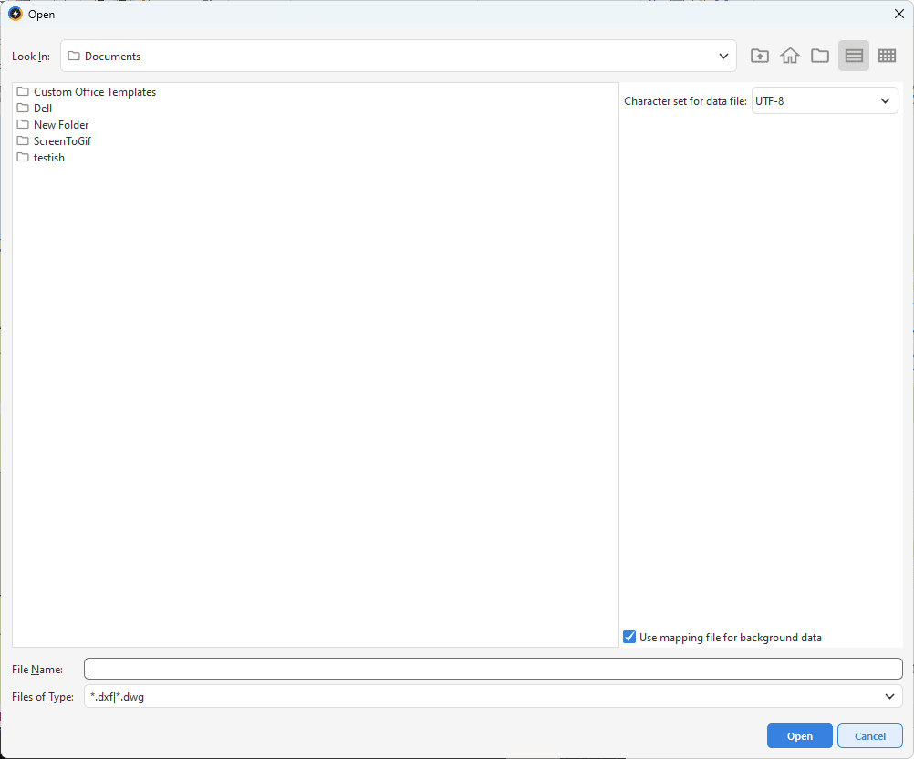
2.Select the desired DXF or DWG file in the dialog box.
3.Press Open.
4.Save the draft mapping file.
5.Open the mapping file in a text editor and complete with mappings to dpSpatial components.
|
Use the Object Metadata Reader function in the administration menu to identify the correct object and component types. |
Create a mapping file manually
1.Create a new text file in, for example, Notepad.
2.Specify the sections [DATA], [GRAPHIC], [TEXT], [SYMBOL].
3.Write the names of the layers from the DWG/DXF file to be mapped.
|
Pay attention to spelling and spaces. All fields and the equal sign are separated by a space, except in the DATA section where no spaces should be used. |
4.For each DWG/DXF element, map the corresponding object and component in dpSpatial
|
Use the Object Metadata Reader function in the administration menu to identify the correct object and component types. |
5.Enter the primary component (main_ctype) and any coordinate system (coordsys) if applicable, in the DATA section.
6.Save the text file. Give the mapping file a name that describes the type of layer, the date and possibly also the area, for example "MappingRealestate102007.txt".
Character set for data file and mapping file
When creating or importing DXF/DWG files, you may need to select the character set for both the data file and the mapping file. This is done in the respective dialog box.
•UTF-8 - Character encoding used to represent text encoded in Unicode. Supports most characters available.
•ISO-8859-1 - Character encoding used to represent text. Supports Western European and Latin characters.
•IBM850 - Character encoding used to represent text in DOS. Supports essentially the same characters as ISO-8859-1.
Import DXF/DWG file
Once the mapping file is ready, the DXF- or DWG file can be imported.
|
There is no tool to remove imported DXF or DWG background data. Please contact Digpro for assistance if you need to clean or update. |
1.Create a changeset for the import. If you are not satisfied with the result of the import, you can always undo the changeset, adjust the mapping file and import again.
2.Select File > Import > DXF/DWG > DXF/DWG....
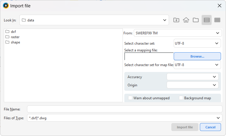
3.Select the DXF or DWG file and its mapping file.
|
You can import several files at once. |
4.Specify character set for data and mapping file (UTF-8, ISO-8859-1 or IBM850).
5.Check the Warn about unmapped box to see which elements have not been mapped. These are shown at the bottom of the import log.
6.If you are importing background data, check the Background map box. The import will then be much faster.
|
To import as a background map, a primary component must be specified in the mapping file and you must be working in a pessimistic changeset. |
7.Press Import file.
|
Check the result before posting the changeset. Adjust the mapping file and re-import if necessary. Pay particular attention to spelling and to the presence of a space between all fields and between fields and equal signs, except in the DATA section. |
Import of object types other than background map
It is possible to import object types other than the background map, but the method is slightly different from normal loading:
•In the mapping file, no primary component is specified in the [DATA] section for the included objects. The program itself identifies the correct primary components during import, which slows down the import.
•Each layer can only be mapped to one component type. If the same layer is mapped to several component types (e.g. both SYMBOL and GRAPHIC), several objects are created.
Example: A DXF culvert layer can be mapped either as a symbol component or a graphic component. If the layer is mapped in both the SYMBOL and GRAPHIC sections, two separate culvert objects are created on import, even though in the DXF file it was a single object.
|
Uncheck Background map when importing other object types. |