In this section, you build a new electricity network in the map by placing a substation, two cable pillars, delivery points and cables. All objects should be placed in state In use.
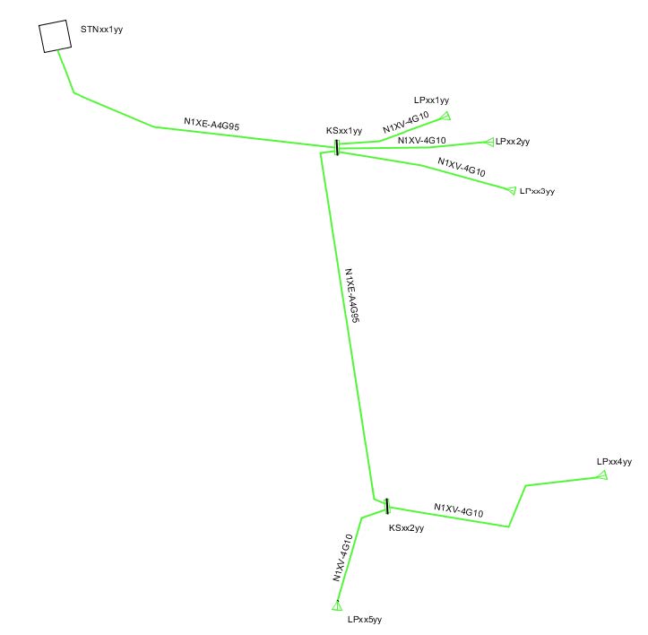
The network to be drawn should look something like this:
Place substation
1.In the sidebar, Map tab, select a map view in the top drop-down menu.
2.Navigate to an appropriate area on the map where the network will be built.
3.In the sidebar, tab Place object, select the map type Geographical map in the upper drop-down menu.
4.Select the folder 10 kV > Stations > Substation secondary ground, 10 kV.
5.Set State to In use and check Show attribute form.
6.Press Place object.
7.In the attribute form, enter the ID and press OK.
8.Place the station symbol in the map, rotate the symbol and place the text label.
Place feeder cable and first cable pillar
1.In the sidebar, Place object tab, select 0.400 kV > Lines > Feeder cable ug, 0.400 kV.
2.Set State to In use and set Placement to Free.
3.Press Place object.
4.In the attribute form, enter Line type SE-N1XE-AS4G95 and press OK.
5.Place the cable from the secondary substation to the planned cable pillar, right-click and select Create component.
6.In the sidebar, tab Place object, select 0.400 kV > Cable pillar > Cable pillar feeder, 0.400 kV.
7.Press Place object.
8.In the attribute form, enter the ID and press OK.
9.Place the cable pillar in the map.
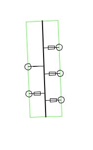
Configure cable pillar
1.In the sidebar, Place object tab, select 0.400 kV > Cable pillar > Cable pillar Busbar, 0.400 kV.
2.Place the busbar by selecting the cable pillar and entering the start and end point.
3.In the sidebar, Place object tab, select 0.400 kV > Cable pillar > Fuse, 0.400 kV.
4.Set Placement to From a busbar, create bay.
5.In the attribute form, enter Fuse type 0.4 / 20 / [xxx] and press OK.
6.Place the fuse on the busbar.
7.Repeat so that you place a total of four fuses on the busbar.
8.In the sidebar, Place object tab, select 0.400 kV > Cable pillar > Other disconnecting devices, 0.400 kV.
9.Set Placement to From a busbar, create bay.
10.Place the other disconnecting device on the busbar.
Place connection points
1.In the sidebar, Place objects tab, select 0.400 kV > Nodes > Delivery point 0.400 kV including service cable.
2.Set State to In use and check Placement loop.
3.In the attribute form, tab Delivery point, enter the ID and address.
4.In the attribute form, tab Service cable ug, select Line type SE-N1XV-U4G10 and press OK.
5.Place the delivery point connected to a fuse in the cable pillar.
6.The attribute form for the next delivery point opens automatically. Enter a new ID and press OK.
7.Place the delivery point connected to the next fuse.
8.Repeat once more so that three delivery points are placed, each connected to a fuse in the cable pillar.
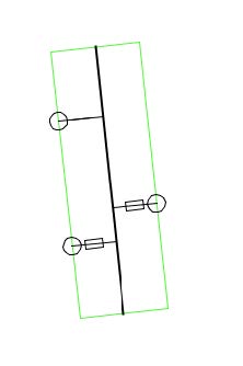
Place the second cable pillar
1.Place a cable pillar under the first cable pillar.
2.Place the busbar, two fuses (Fuse type 0.4 / 16 / [xxx]), and one other disconnecting device in the same way as in the first cable pillar.
3.Place a feeder cable with location between nodes and Line type SE-N1XE-AS4G95 between the two cable pillars.
4.Place two delivery points each connected to a fuse in the same way as in the first cable pillar.
Place cable texts
1.Select Place > Line texts > Line text 1.
2.Place texts for all cables in the network.
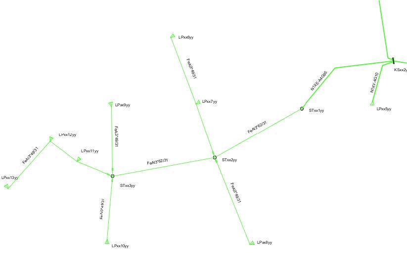
Connect overhead line to cable network
This section describes how to connect an overhead line network to the cable network above by placing poles, joints, delivery points and lines in the map.
Place poles and pole joints
1.In the sidebar, Place object tab, select Poles > Pole, LV and place three poles.
2.In the sidebar, Place object tab, select 0.400 kV > Nodes > Joint OH-UG, Feeder cable, 0.400 kV.
3.In the attribute form, enter Object category Pole joint.
4.Place the joint in the first pole.
5.Place a Branch Joint, Feeder cable, 0.400 kV with Object category Pole joint in the other two poles.
Place delivery points and connect to cable pillar
1.Place eight delivery points in the appropriate positions.
2.In the second cable pillar, place a new 50 A Fuse, 0.400 kV for connection to the overhead network.
3.Place a Feeder cable ug, 0.400 kV between the cable pillar and the first pole. Select the appropriate line type.
Place overhead lines and service cables
1.Place a Feeder cable ug, 0.400 kV between the joints of the first and second pole, use Placement Between nodes and select the appropriate line type.
2.Place Service cable ug, 0.400 kV to all delivery points, use Placement Between nodes and select the appropriate line type.
Place line fuses and cable texts
1.Place Line fuse, 0.400 kV, 20A between joints in pole and service cables, use Placement Between nodes.
2.Place line texts for all lines via Place > Line texts > Line text 1.