This section describes how the connection form in dpCom works and the procedure for connecting and disconnecting optic fibers or copper wire to/from equipment in a node or to/from other cables. The connection forms are standardized and looks the same for any type of applicable objects you wish to connect. The only difference is the set of object types that you work with.
|
Column settings that is being made in the connection form is saved automatically. |
The description that is given here is general and is applicable for the connection procedure with all types of opto fiber, copper cables and connectors or ports in passive and active units such as ODF:s, switches and converters. The table below will give you an overview of the existing connection tools, the type of connections that can be handled and how to start the tools.
Overview
Tool |
Icon |
Connections |
Start the function by selecting: |
Optic fiber (Edit > Fiber) |
|
|
|
Splice fiber |
|
▪fiber >< fiber |
Node, Rack, Fiber joint closure, Joint in rack, ODF or Passive equipment |
Connect fiber |
|
▪fiber >< connector in ODF unit ▪fiber >< connector in converter module ▪fiber >< port in switch unit ▪fiber >< contact in active equipment port ▪fiber >< contact in passive equipment
|
Node, Rack, ODF, Converter frame, Fiber split frame, Active equipment, Passive equipment |
Connect fiber to front of ODF |
|
▪fiber >< connector in ODF unit ▪fiber >< contact in passive equipment |
Node, Rack, ODF, Passive equipment |
Patch fiber |
|
Any combination of: ▪connector in ODF ▪port in switch unit ▪fiber split module in fiber split frame, ODF or Passive equipment ▪connector in converter module ▪contact in active equipment port ▪contact in passive equipment
|
Node, Rack, ODF, Converter frame, Fiber split frame, Switch, Active equipment, Passive equipment |
Patch on the inside of ODF |
|
Any combination of: ▪connector in ODF ▪fiber split module in ODF or Passive equipment ▪contact in passive equipment
|
ODF, Passive equipment |
Copper thread/carrier (Edit > thread/carrier) |
|
|
|
Splice thread/carrier |
|
▪thread/carrier >< thread/carrier |
Copper joint closure |
Connect thread/carrier |
|
▪thread/carrier >< distribution point socket, copper contact in active equipment port, connector in converter module |
Node, Rack, Distribution point, Active equipment, Converter frame |
Patch thread/carrier |
|
Any combination of: ▪distribution point socket in distribution point ▪connector in converter module ▪copper contact in active equipment port
|
Node, Rack, Distribution point, Active equipment |
Duct (Edit > Duct) |
|
|
|
Connect ducts |
|
▪(micro)duct >< (micro)duct |
Node or Duct joint closure. See section Edit > Duct > Connect ducts |
Connect
|
If the table of connectable objects is empty, it means that: •The selected device or cable has no free objects, i.e. all fibers / wires / contacts / have already been connected. •Incoming objects for the selected device have not been generated, for example a cable lacks input fibers. See also the section: Generating fiber, wire, contacts or ducts. |
1.Select Edit > Fiber or Thread/carrier > Connect [fiber or thread/Carrier].
2.Select object in the graphic view. The connection form opens.
3.Select a device (ODF, switch, etc) or a cable in each of the drop-down lists on the left and right of the top of the form. The tables below now show free and connectable objects.
4.Select the included objects to be connected - fibers / contacts/ distribution points/ ports - in the two tables on the left and right. Press Ctrl and SHIFT to select multiple rows. Ctrl + A selects all objects in a table.
|
You must select the same number of objects in each table if you connect optical objects. In the bottom of the connection form, you can see how many rows you have selected. |
5. The button for connecting is placed between the left and the right sections. Select an even number of rows on both the left and right sides, then press Connect. The objects are now connected and moved down in the lower table of the form Connections in [node / unit].
The Connection form
The connection form is divided in main sections:
•In the upper part of the connection form there are two tables that contain available and connectable objects that can be connected to each other. There are also tool buttons for working with specific tables of available and connectable objects, located directly adjacent to each respective table.
•In the lower area, a table of existing connections / splices between objects in the fields is displayed. The lower table in the connection form shows which objects are already connected in the selected node / device. Each row corresponds to a physical connection (fiber path): On the left side, fiber / wire is shown, and on the right side the contact / terminal / fiber to which the object is connected / spliced. There are cases where two rows in the connection table correspond to a physical connection. For example, between an ODF unit and a Switch unit, 2 ODF connectors can be connected to a port in the switch. There is also a toolbar with functions for managing the connected objects.
•At the top of the connection form, the name list is displayed with information about, for example, the selected connection tool, the selected node name, and the selected address.
•The buttons in the toolbars of the connection form give you quick access to the most common tools you need to edit, customize and export information about connections in a node or device. To access other functions, right-click on an object in the link form and select one of the object-specific menu options displayed in the right-click menu.
Tables with connection fields
The two tables in the upper part of the connection form displays fibers, wires and connectors that are not connected to any other object, and therefore available or "free" to connect. Depending on the connection form that has been activated and the object selected (node, rack, ODF, distribution point), eligible objects may be found to the left in the drop-down list and to the right in the drop-down list.
The content of the drop-down lists is determined by the following:
▪The connection tool used e.g. if you have selected Patch fiber, the ODF units and the switches are the only thing visible in the tables since it is only possible to patch between or within these object types.
▪The object you selected to open the connection dialog. The choice controls the selection of cables or units. Suppose you want to perform patching in a major node in the network: You activate the connection tool Patch fiber and then select...
...a distribution node |
All the ODF units that exists in the node will be displayed in the drop-down lists. See the section Filter below for more information |
...a rack (in a node) |
All the ODF units that exists within the rack will be displayed in the drop-down lists. |
...an ODF |
Only the selected ODF unit will be displayed in the drop-down lists. (for patching within the ODF unit) |
Settings
Drop-down lists (left) and (right) |
Contains a list of available device/cable objects. If you have applied a filtering option, the contents of the list may change. Units are presented with information about Object type, id, and parent object. Cables are presented with information about Cable type, id, and to which object (ODF, splice, etc) the cable is connected at the other end, connected to [object id]. Included objects that are not linked are shown in tabular form in the main field below. |
||||||||||||||||||||||||||||||||||||||||
Filter |
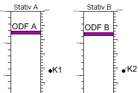
Use the filter options to filter out valid objects to connect in the opposite drop-down list. Example: If you have chosen to connect fibers in the cable object K1 and selected the filtering option, ODF A, but not ODF B, will be available in the drop-down list on the right, because in this case fibers in K1 cannot be connected to ODF B. The example is valid if you chose to open the connection form via a node object. If instead you opened the connection form via a rack object - for example "Rack A", then only ODF units in that rack will appear in the drop-down lists.
|
||||||||||||||||||||||||||||||||||||||||
Number of selected lines (from/to) |
Shows the number of selected objects in the left and right table. For connections and splices between fiber and ODF connectors, the number must be the same on both sides. When connecting copper wire, however, the connection ratio can be one to many. The same applies to connection to the switch and converter unit. |
||||||||||||||||||||||||||||||||||||||||
Load end object |
Show which device and in which node the objects are connected to, via splices and patches in the network, their termination at the other end of the fiber path. The information is loaded and displayed in the End Object columns. Use the function to identify the fiber/wire that has the desired end node/rack/device. Example: Load end objects if you are connecting/patching in a central or distribution to connect connecting nodes (customers) to make sure you select the right fiber/wire on the current cable. If a field is empty in the End object column, it means that the fiber/wire path is not terminated (connected) at the end. |
||||||||||||||||||||||||||||||||||||||||
Toolbar |
|
||||||||||||||||||||||||||||||||||||||||
Load services |
Displays the connection and any services added to the fiber / thread. The information is loaded and displayed in the Connection columns. |
||||||||||||||||||||||||||||||||||||||||
Load end object |
Shows which units and nodes the objects are connected to at the end of the route, via any connections, splices and patches. The information is loaded and displayed in the End Objects columns. |
||||||||||||||||||||||||||||||||||||||||
Load ducts and pipes |
Displays pipe or duct in which cable is located (new column Duct / pipe ID is displayed). |
Disconnect
1.To disconnect objects, select the contained fibers/connectors/distribution points/ports you wish to disconnect and press the button Disconnect ![]() in the toolbar.
in the toolbar.
2.The disconnected objects are transferred to the upper tables containing unconnected objects.
Connection with service
To disconnect an object with service you get a warning that states that the selected connection has a service.
If answering Yes in the dialog, the disconnection will occur and the row disappears from the lower dialog. If answering No, the operation will be canceled.
|
This behavior is configurable. If an object has a service attached to it, and shall not be edited in this way, it is possible to settle through configuration. The standard behavior, however, is that it is possible to connect / disconnect even after service. |
More information
Export connections to spreadsheet
To save the connections in the connection table in a spreadsheet (e.g. Excel or Open Office), use the button Export to spreadsheet ![]() from the toolbar in the connection form. When exporting to excel you can customize which columns that should be included and how the result should be sorted and presented:
from the toolbar in the connection form. When exporting to excel you can customize which columns that should be included and how the result should be sorted and presented:
Select the columns that should be included in the export. The columns that are available depend on the object types that are shown in the connection table when you choose to export. If you are exporting from Connect fiber for example, the attribute columns for Cable, Fiber, ODF, Connections and Services are shown.
The columns displayed in the connection table are preselected. Select a checkbox or deselect a column.
Export options
Add header information |
Adds information about the User, Date and Report type at the top of the spreadsheet. |
Add node information |
Adds information about the Node-ID and address at the top of the spreadsheet. |
Group object based on parent |
Groups for example all the connections/splices of fibers that belongs to the cable or groups all the microducts that belongs to the multiduct. Each group is presented in alphabetical order, with column headers and is separated by a blank line. |
Repeat column header |
This checkbox is activated when the option Group object based on parent is checked. Repeat column header repeats the column header in the exported file. |
Alternating row color |
Fills every other row with a light gray fill color. |
Filter connections
To facilitate handling and editing of all performed connections, there are filter options that allow you to display only objects of a certain type, stage, end object, etc.
1.Press Edit in the toolbar to display only the link table and make it easier to read and work with.
2.Press the Filter icon on the far left of the toolbar to show or hide the filter options.
Splice cables in ODF
It is also possible to splice two cables together in one ODF. The ODF then functions in the same way as a splice object. This function is used if you want to "pick out" for example 4 fibers out of 12 and connect to contacts. The remaining 8 are spliced straight towards each other and continue from the ODF unit.
To perform such a type of cable splitting, use the Connect Fiber function in the ODF. The other 8 fibers are spliced together using the Splice fiber function.
Error dialog during connection / splicing
In some cases, it is not possible to carry out a connection or splicing. This can be due to the fact that one of the objects in question is locked, broken, or that the coupling violates the coupling rules.