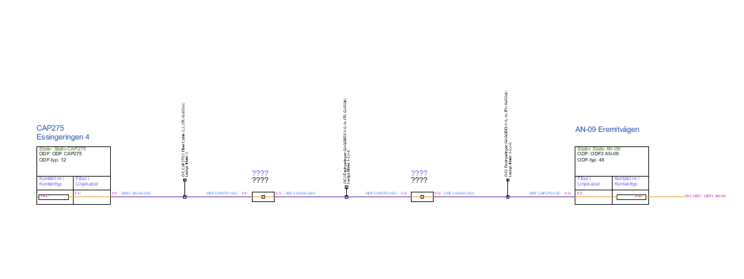
Generates a schematic diagram showing the fiber from each connector and its path from point A to B, as well as connected fibers that have no final destination, so-called "backstops".
The fiber diagram is generated completely dynamically according to the user's wishes. The user specifies the start ODF as well as the end ODF for the fiber diagram. The fiber diagram contains information about nodes/APs, stands, ODFs, connector types, addresses, cable types, splices and splitters.
Generate fiber connection diagram
1.Select Reports > Fiber connection diagram.
2.Select starting object: left-click on a node, stand or ODF. The Generate fiber connection diagram window opens.
3.Select the start object on the left and then the end object on the right.
4.Press OK to generate the fiber diagram, which appears in a new window.
Example