A duct connection diagram shows the route of a selected multiduct or pipe (start and end node), how the constituent ducts are branched into duct joint boxes, connected and connected at nodes along the route.
Generate duct connection diagram
1.Select Reports > Duct connection diagram.
2.Left-click on the multiduct or pipe (containing ducts/micropipes) in position map for which you want to see a duct connection diagram. A duct connection diagram is automatically generated and displayed in a new window, see example below.
Example
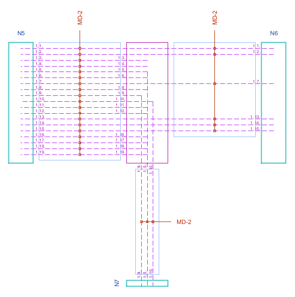
Duct connection diagram for a multiduct (Detail):
•Solid lines show ducts containing fiber. The crossed out ones are empty of content.
•Microduct attributes are Lap/Order/Color, e.g. the highest (blank) duct is identified as "Round 2, Order 3, Color (blank)"
•The objects in the duct connection diagram are active: right-click an object to display the right-click menu with object-specific menu options.