About ducting
Ducting can consist of pipes, sub pipes and ducts. Since all types of ducting (and cabling) in dpCom are always placed in routes, the routes are also included in the ducting concept.
Route is a generic term for the different types of roads and channels in which pipes, ducts and cabling can be routed. Outside routes can consist of for example a trench (shaft, cable burial, pit line) if the placement is in the ground or aerial if the placement is through an aerial route. Indoor routes refer to all types of roads that built-in or surface-mounted ducting and cabling follows, for example through pipes, pipe-like channels, ladders and consoles.
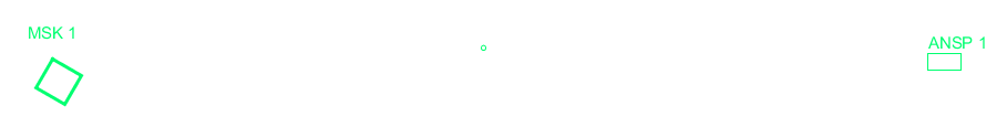
Place nodes or manholes
In dpCom the placement of routes should always take place between nodes or manholes in the map. Make sure that you have placed the distribution nodes, customer nodes or manhole types that the ducting should run between.
1.Open the sidebar ![]() .
.
2.Select the Place objects tab.
3.Select objects under Nodes/manholes/poles with split of route.
If you are uncertain on what type of node or manhole to use, you can place an Event node in the map instead. You can at any time easily replace the Event node with another node type by: using the tool Edit > Node/manhole > Change type of node. See section Change type of node.
1.In the menu, select Edit > Node/manhole > Change type of node. See section Change type of node.
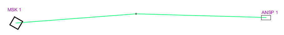
Create route between nodes/manholes in the map
Once you have the nodes/manholes in the right position you can place a route that connects them together. The route is the shaft or the aerial line that pipes and cables runs through between two nodes. It is the route that provides the pipes and cables with their graphical location, extent and length in the map.
There are a wide variety of routes to choose from, the main classification for routes are Uncertain location and Measured. The most common is to document the route as Uncertain location and then correct the position when receiving an input file from field staff. See section Adjust placement of route below.
There are several functions that makes the placing of routes easier when placing them in the map. Among other things it is possible to parallel copy all the graphic or parts of it in the map and thus place a route at a given distance from a roadside or sidewalk. Additional placing alternatives are described in section Place objects and components.
1.Open the sidebar ![]() .
.
2.Select the Place objects tab.
3.Select objects under Route.
Place content in route
When nodes/manholes and routes are documented in the map it is time to add some content to the routes. In dpCom you have access to several different types of pipes and ducts which you place in the map to document how it looks in the network.
Everything that is placed in the route will be shown in the cross section:
Pipes and sub pipes
Pipes and sub pipes are used in dpCom as ducting and protection for opto - and copper cables. Air blown fiber, multiduct and micro ducts, which mainly applies for FTTH, is handled in a different way than traditionally drawn opto cables which are placed in pipes/sub pipes. See section Working with ducts.
The most common is to place pipes that protects the cable/s that runs through a route, but it is also possible to place the cables directly in a route without protective ducting.
Pipe is in the typical case, some type of constant ducting (concrete or plastic) with an inner diameter of 95 mm, 50 mm or less.
Sub pipe is a type of light pipe that is used to protect the cable. The type is less sustainable than ducting pipes, with an inner diameter of 50 mm or less. Sub pipes is usually placed in a pipe to show that there is some extra protection for the cable. Sub pipes can also be used as single/simple ducting.
1.Open the sidebar ![]() .
.
2.Select the Place objects tab.
3.Select objects under Pipe.
Dimensions on pipes and sub pipes
It is possible to specify the exact inner and outer diameters of pipes and sub pipes in the attribute form. The measurements are handled by the system administrator by editing the relevant code lists. In the map, the pipes and sub pipes are represented as circles in the cross section graphics for the route. Pipes are shown as big circles and sub pipes are shown as smaller circles. Approximately 5 sub pipes fits graphically inside a pipe.
Placing alternative
Pipes and sub-pipes can be placed directly in the route. If there are already pipes in the route, the new pipe is drawn next to them, or they can be placed inside an existing pipe in the route. Typically, a sub-pipe is placed inside a pipe.
Directly placed cable
An opto cable and copper cable can be placed inside a protective pipe or sub-tube, or directly in the route.
1.Open the sidebar ![]() .
.
2.Select the Place objects tab.
3.Select objects under Optical network > Cables or Copper networks > Cables.
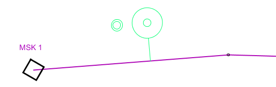
Cross sections
A cross section is a type of graphics that shows the content of a route, it is a graphical component that belongs to a route object in the map. A cross section can display symbols for pipes, ducts and cables that are placed in the route. It is possible to place multiple cross sections to the same route to show the contents of a route that runs unbroken in the map. It is also possible to delete cross sections and update the current cross sections.
You can use the cross section to, for example, place a cable and a sub pipe inside other pipes or to remove pipes from cables in a route.
Show cross section
To make it easier to work with the content of a route, you can display the cross section in a separate view.
1.Right-click on a route and select Show cross section and choose between Show in other view, Show in new window or Show in active view.
Another way to view the contents of a route is by opening the attribute form for the route. It displays graphics of the content in the route in an automatically generated cross section.
1.Right-click on a route and select Show/change attributes.
Cross section:
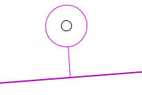
Place a cross section in the map
The first time you place a pipe, a duct or a cable in a route, you are also placing a cross section somewhere on the route. To place an additional cross section in the map:
1.Select Place object > Route > Cross section.
|
You can also right-click on a route and select Object > Place cross section. |
2.Select a route. The cross section is shown next to the mouse cursor
3.Adjust the placement of the cross section by moving the mouse cursor. The cross section can be placed anywhere along the route. You can decide how the pipes/ducts/cables is suppose to be placed in the route, next to or on top of each other.
4.Click again when you are satisfied with the placement.
|
To change placement of a pipe, use the function Edit > Pipes and routes > Swap pipes. |
Delete cross section
1.Select Delete component ![]() in the tool bar and click on the reference line that belongs to the cross section graphics.
in the tool bar and click on the reference line that belongs to the cross section graphics.
|
The cross section is a graphical component that belongs to the route and is only representing those objects that are placed in the route, so when deleting the cross section, the reference line, you do not delete the objects that are shown in the cross section. |
Update a cross section
Some functions that affects the contents of a route can make the cross section outdated, it does no longer show the right content of the route. The graphic in the attribute form of the route is always showing the right content, so use that if you are uncertain.
1.Select Move component ![]() in the toolbar, then click on the reference line associated with the cross-section graphic.
in the toolbar, then click on the reference line associated with the cross-section graphic.
Alternatively:
1.Right-click on the route and select Update Cross Section.
Adjust placement of a route
To adjust the placement of a route, there are the simpler editing tools in the toolbar, which allow you to add, move and remove breakpoints on the line and thus change its route in the map. Those tools are best suited for minor adjustments.
If you want to make more extensive edits, for example correcting the position of a route based on a survey that has been carried out in the field, here is a description of how to replace a planned route with a routes real position using a loaded reference file:
1.Load the reference file that contains the survey of the route, for example a DXF-file, with File > Reference data > Open reference file.
2.Check the checkbox Fit view to file to zoom the map to show the reference file. The location becomes available as a bookmark under Window > Bookmarks > 'Name of file'.
3.Select Place object > Free graphics > Free postable graphics.
4.Press the button Place object.
5.Right click and select Offset whole line object.
6.Select the line/object to copy by clicking on the route from the loaded file. Multiple choices may be displayed. Select the correct one by holding the mouse over the text, which will make the various objects light up.
7.Set the distance to 0 m to place the free postable line on top of the loaded route.
8.Select the side from which the line should start to be drawn and from which you should start when copying. The first part is drawn in the map.
9.If the object is divided in several parts, right click again and continue Offset whole line object and select the next part of the route until you have reached the goal.
10.Double-click or right-click and select Create component. Now there is a line placed on top of the route of the loaded file and you just have to replace it with your route.
11.In the menu bar, select Edit > Pipes and routes > Change geometry on route.
12.Select the route to replace geometry for, meaning the route to be moved.
13.Select the line to copy, meaning the line that shows the true position of the route. The planned route is now moved to the survey location. Any content in the planned route is included, but you need to update the cross section to its right location, for example with the function Move component with links.
14.Change the subtype of the route from Uncertain location to Measured by in the menu bar, select Edit > Objects > Change subtype.
Edit content in a route
The sub menu Pipes and routes under the menu Edit, contains a lot of tools that in different ways allows you to edit routes, pipes, ducts and cables in the network. You can for example extend the placement of a pipe, remove cable/pipe from a route, join pipes, split routes and a lot more. You can read more about these tools and other editing tools in the section Menu reference > Edit > Pipes and routes.