Report “HV Earth Fault”
Substation term:
•Substation ID.
Transformer terms from left to right:
Row 1
•Node point ID.
•Single phase to earth fault current, (A).
•Resistance at high-Ohm earthfault. Standard value can be set with a configuration file (currently 3000 Ohm).
•Single phase to earth fault current, (A), at high Ohm earth-fault.
Row 2
•Capacitive earth fault current, (A).
•Capacitive earth fault current, (A) at high-Ohm earth fault.
Row 3
•Neutral point voltage kV at high-Ohm earth-fault.
•Phase voltage kV for healthy phases at high-Ohm earth-fault.
•Phase voltage kV for faulty phases at high-Ohm earth-fault.
Row 4
•Neutral point voltage kV at rigid fault.
•Phase voltage kV for healthy phases at rigid fault.
Bays / Feeders, Technical Terms from left to right
•Bay ID
•Capacitive earth fault current A
•Single phase earth fault current A
•Capacitive earth fault current A at high Ohm earth fault
•Single phase earth-fault current A at high-Ohm earth fault
•Sum of conductor earth capacitances from upper side A
•Sum of conductor earth capacitances from lower side A
•Sum of other capacitive current in neutral points from upper side A
•Sum of other capacitive current in neutral points from lower side A
•Sum of current from neutral point reactors from upper side A
•Sum of current from neutral point reactors from lower side A
•Sum of reactive current from upper side A
•Sum of reactive current from lower side A
Report on conductor level
All represented result terms are for a node-point ID. From left to right, these terms are as follows:
•Bay ID
•Node point ID from
•Node point ID to
•Sum of conductor capacitances from upper side, A
•Sum of conductor capacitances from lower side, A
•Sum of other capacitive current in neutral points from upper side, A
•Sum of other capacitive current in neutral points from lower side, A
•Sum of current from neutral point reactors from upper side, A
•Sum of current from neutral point reactors from lower side, A
•Sum of reactive current from upper side, A
•Sum of reactive current from lower side, A
•Sum of resistive current above upper lying reactors, A
•Sum of resistive current under lying reactors, A
Extract from theoretical description
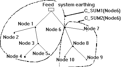
Illustration of contribution to earth fault current, e.g. earth fault in Node6 (considering also local neutral point compensation out in the network)

The conductors zero sequence capacitances (re-calculated to capacitive current for printouts):
C_SUM1 = Contribution from the above lying part of the network
C_SUM2 = Ditto for the underlying (summarized to the from-node points)
Other measured capacitive current:
AICSUM1 = Contribution from above lying part of the network
AICSUM2 = Ditto from the underlying network
The neutral points reactor susceptance's (re-calculated to inductive current for printouts):
AILSUM1 = Contribution from above lying part of the network
AILSUM2 = Ditto from the underlying network
Sum of reactive current (capacitive current less the inductive current):
AISUM1 = Contribution from above lying part of the network
AISUM2 = Ditto from the underlying network