Perform geodetic coordinate calculations such as resection, orthogonal alignment and polar alignment.
Geodetic coordinate calculations
Resection
The method determines the planar position of the point by measuring length between a new point and two known points. The purpose of the method is to be able to calculate coordinates for a new point using known point coordinates.
1.Choose Tools > Geodesy. The Geodesy dialog box opens.
2.Zoom in to the current area.
3.Select the Resection tab.
4.Enter the coordinates of the station point (X Y) by clicking on a desired position on the map or enter the coordinates using the keyboard.The position of the point should now be shown on the map with two temporary circles and coordinate values transferred to the fields Station point X, and Station point Y.
5.Target point is stated in the same way as above. The position is shown in the graphic with two temporary circles and the coordinates are transferred to the fields Target point X and Target point Y.
6.To get the coordinate values of the new point: First select the Left or Right selection box to decide which page the searched point should end up on. Enter a value in the field for Distance 1. Enter a value in the Distance 2 field.
If the values in the distance fields are too small, the length or angle becomes too small and no results are obtained. (status bar: New point can not be calculated). Set a larger value to get results.
7.The searched point should now appear on the map as a temporary circle to the left or right of the known points depending on how you have selected according to step 5.
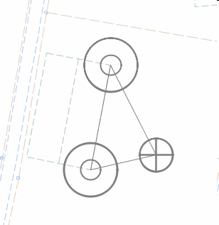
The result of the resection in the graphical view.
Settings
Station point X Y |
First known point. |
Target point X Y |
Second known point. |
Distance |
Refers to the distance between known points and the new point. Mean error 1 mm / m below 10 m and 25 mm at 50 m distance. Conclusion: At short distances and on a flat surface, the resection method can give results with acceptable measurement errors. |
Distance 1 |
Is the distance between the station point and the searched point. |
Distance 2 |
Is the distance between the Target point and the searched point. |
Left |
Determines that the searched point ends up on the left side of the direction from station point to target point. |
Right |
Determines that the searched point ends up on the right side of the direction from station point to target point. |
Orthogonal measuring
The method is used when a fixed solution is not available. This method is based on a baseline. The baseline is started from a known base point towards a known target point.
The searched point is determined by two polar measurements that follow each other.
1.Choose Tools > Geodesy. The Geodesy dialog box opens.
2.Zoom in to the current area.
3.Select the Orthogonal measuring tab.
4.Enter the coordinates of the station point (X Y) by clicking on a desired position on the map or enter the coordinates using the keyboard.The position of the point should now be shown on the map with two temporary circles and coordinate values transferred to the fields Station point X, and Station point Y.
5.Target point is stated in the same way as above. The position is shown in the graphic with two temporary circles and the coordinates are transferred to the fields Target point X and Target point Y.
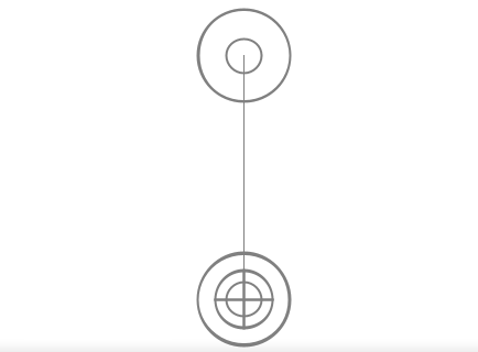
6.To get the new point's coordinate values, do the following: First select the Right or Left selection box to get positive or negative ordinates. Enter a value in the Abscissa field to determine the length along the baseline. Enter a value in the Ordinate field to determine the length across the baseline. If everything is OK, the result position is presented with a temporary circle in the graphic. The result in the graphical view can look like this:
The result of orthogonal measurement in the graphical view.
Settings
Baseline |
The line formed between two known assisting points is called the baseline. |
Abscissa |
Measurements along the baseline are called abscissa. |
Ordinate |
Measurements across the baseline are called ordinates. |
Right |
Choose the right direction to get positive ordinate. |
Left |
Select left direction to get negative ordinate. |
Station point |
Known base point A which forms the first point in the baseline. |
Target point |
Known target point B which forms the second point in the baseline. |
Polar measuring
The method is used when there are two points with a sight line between them. The measuring instrument is placed over one point and the prism over the other point. Distance and angle measurement are made from the sight line. In this method the angle and length of sight line are important.
1.Choose Tools > Geodesy. The Geodesy dialog box opens.
2.Zoom in to the current area.
3.Select the Polar measuring tab.
4.Enter the coordinates of the station point (X Y) by clicking on a desired position on the map or enter the coordinates using the keyboard.The position of the point should now be shown on the map with two temporary circles and coordinate values transferred to the fields Station point X, and Station point Y.
5.Target point is stated in the same way as above. The position is shown in the graphic with two temporary circles and the coordinates are transferred to the fields Target point X and Target point Y.
6.Select the Gon or Degrees options.
7.Enter value for Horizontal angle, vertical angle and Slope distance.
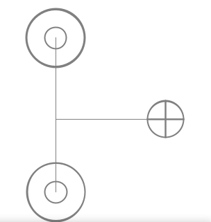
If everything is OK, the result position is presented with a temporary circle in the graphic. The result in the graphical view can look like this:
The result of polar measurement in the graphical view.
Settings
Sight line |
The line formed between station point and target point with sight line in between. |
H. angle |
Angle measurement between the sight line and north. |
V. angle |
Vertical angle measurement. |
Slope dist |
Length of sight line. |
Station point |
Known base point A where the measuring instrument is stationed. |
Target point |
Known target point B where the prism is placed. |
Intersection
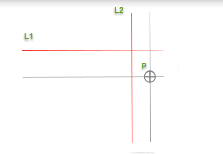
The measurement method is used where length measurement is difficult or impossible to perform. The point P is determined by the intersection of two straight lines.
1.Choose Tools > Geodesy. The Geodesy dialog box opens.
2.Zoom in to the current area.
3.Select the Intersection tab.
4.Enter the first intersection line by selecting or placing a line on the map as L1.
5.Enter the second intersection line by selecting or placing another line on the map as L2.
6.Enter the value of Distance 1 and Distance 2.
The starting point of the line is determined by the nearest coordinate when pointing to the line.
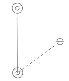
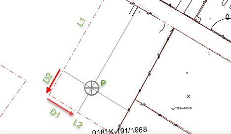
7.The orthogonal lines are drawn and the point P.
If everything is OK, the result position is presented with a temporary circle in the graphic. The result in the graphical view can look like this:
Settings
L1 |
First line indicated on the map. |
L2 |
Second line indicated on the map. |
Distance 1 (D1) |
The distance between the intersection line and L1. |
Distance 2 (D2) |
The distance between the intersection line and L2. |