Fault current analysis for parallel conductors
The fault-analysis of parallel sections is done according to specified rules. The conditions for managing neutral lines can be chosen at the tab Fault-current calculation for the calculation parameters. Select whether or not the neutral line should be broken or intact.
The computer program identifies which kind of parallel-case that should be analyzed. If a parallel-case cannot be identified with a switch case 1-3, then no calculation will be done.
The calculation of the largest allowed fuse is also done and reported for every significant fuse (protecting device). The type and requested tripping times are defined in the calculation parameters.
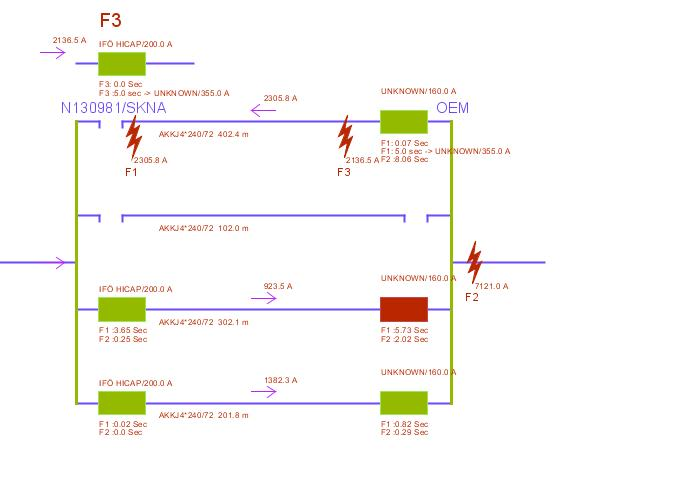
In the auto schematics all information regarding fault case F1 is reported, according to standard.
Fault case F2 is reported with fault current in the to point, and also the tripping time for the fuses in the schematics are presented. As fault case F2 is the “normal” fault position for fault current analysis, all information is obtained in the reports that can be generated.
Also, there’s a special analysis of a third fault case F3 that is performed for parallel sections, where fuses exists in both from and to parts, and where the fuses in the to side is smaller than in the from side.
Note, that in the schematics fault case F1, fault case F2 and fault case F3 is reported. A calculation of the fault in the to-end is always performed and is reported in the relevant report types.
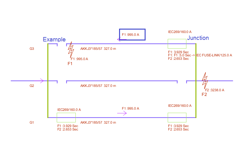
Switch case 1. Fault case F1 and F2
The switch case is identified as case one, a common protection
The fault point is chosen in the worst point (F1), that is, where the fault-current is as lowest. The fuse is checked according to the fault current in the fault location (F1). The check is performed as a calculation of the tripping time for (F1) using the fuse rated data curves. If the calculated time is lower than set time in the calculation parameters an alarm is shown as a color highlighting. Also the fault current in F2 and tripping time for F2 is presented in the schematics.
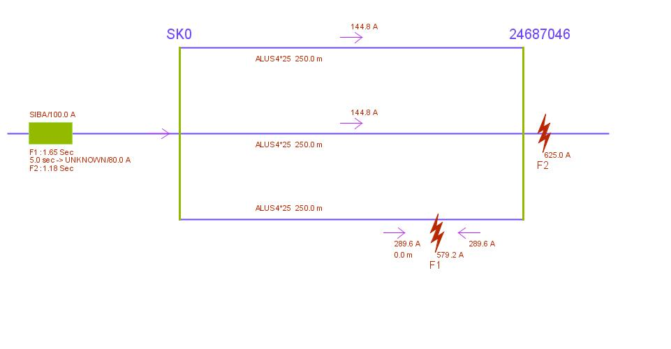
Switch case 2. Fault case F1 and F2
The switch case is identified as case number two. All conductors have a fuse in the from-point. The fault location is found in the section with highest impedance in relation to the from-point considering the closest from-fuse having tripped.
Both the remaining fuses are considered to be protecting and hence checked regarding the fault current in its sections created by the fault in F1. The check is conducted by calculating tripping times using the fuse rated data curves and validated against the set time in the calculation parameters. Also the fault current in F2 and tripping time for F2 is presented in the scheme.
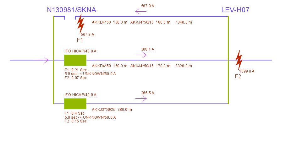
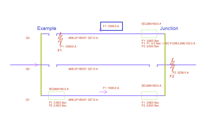
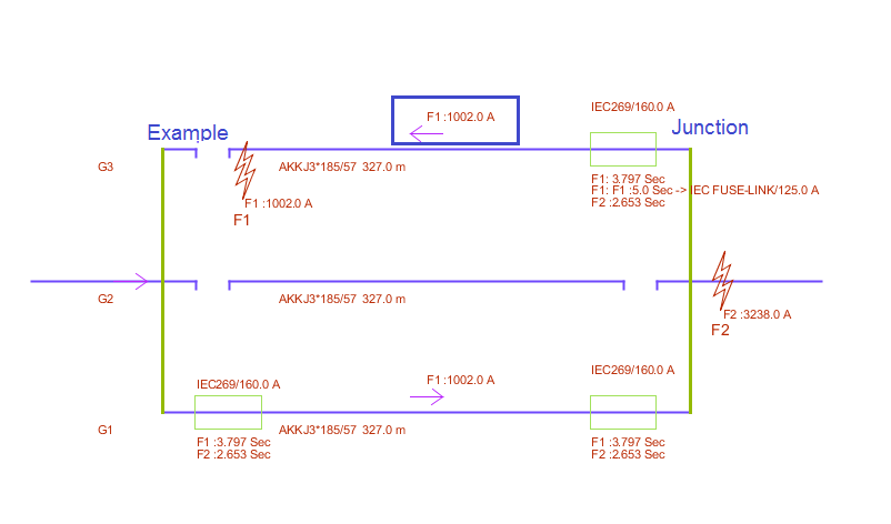
Switch-case 3. Fault case F1, F2 and F3
Fault case F1 and F2
This switch case is identified as three cases. All conductors have fuses in both from and to side and all fuses are equally sized.
The section wit lowest impedance is assumed to have tripped.
The fault is then located in the from-point of the section with highest impedance of the remaining conductors.
The fuse (S1) in the section with the fault is assumed to be the protecting and is checked against the fault-current F1.
The check is performed as a calculation of the tripping time for (F1) using the fuse rated data curves. If the calculated time is lower than set time in the calculation parameters an alarm is shown as a color highlighting.
Also the fault current in F2 and tripping time for F2 is presented in the schematics.
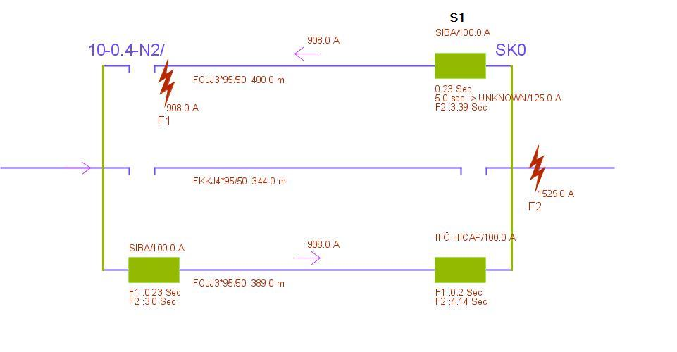
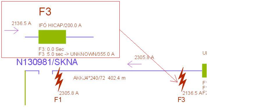
Fault case F3
The switch case is identified as fault case three. The fuses in the to-end are smaller than those in the from end. The presentation of fault case F1 and F2 is done as earlier described.
For this protection combination an extra fault analysis is performed where the fault is located in conjunction to the protection device in the to-end. Now also the from-end protection is checked as if single conductor was used.
The presentation is shown separately in connection to the protection that is controlled.
Control of fault case F2, fault located in the to-point
The fault control regarding faults located in the to-end is always performed as a standard in the normal analysis for both single as well as for parallel sections.
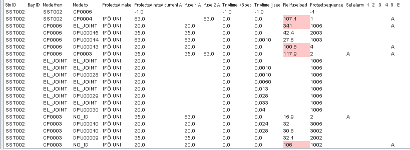
Example from the report LV Fuse report control
Regarding parallel cables with intact neutral in the fault position.
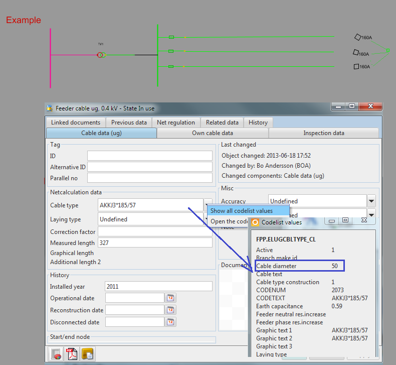
For calculation of earth fault current in parallel cables where the neutral conductor is intact, we must take into account to the mutual impedance between conductors Preconditions are that there is an indication of the diameter of the cables stored in the code list type data, see below.
The formula for the inductance reads L = 0.2 x ln (a / r) + 0.05 [mH / km] where a is the distance between the conductors and r is the radius of the phase.
Conditions
Intact neutral conductor
Information about cable diameter
Testcase
46 mm cable diameter
48 mm cable diameter
50 mm cable diameter