This function is used to visually divide the network from a station into different areas, based on which outgoing bay from the selected station they are fed from.
Each bay area is colored in a unique color, providing a clear overview of the network structure and feeding paths from the chosen station.
Prerequisites for the trace
•Each bay in the selected substation must be connected to a network object, such as a cable or a line.
•The voltage level of the connected network objects must match the low-voltage side of the transformer in the station.
•All objects in the network must be topologically connected and properly linked.
•Switches or disconnectors that are open in their normal state are blocked and excluded from the trace.
Trace network topology coloring - Color bay areas
1.Select a Substation.
2.Select Tools > Trace > Network topology coloring > Color bay areas. The network is now colored with a unique color for each bay. The rest of the network will be colored grey.
3.A possibility to change color is now offered. Each individual color can be changed by pressing the box for that color. The colors can be reset by pressing Reset colors.
4.Reset the graphical view by selecting Window > Refresh (F5) or by pressing ![]() .
.
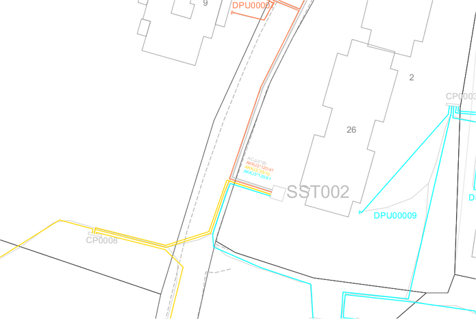
It can look like this in the map view:
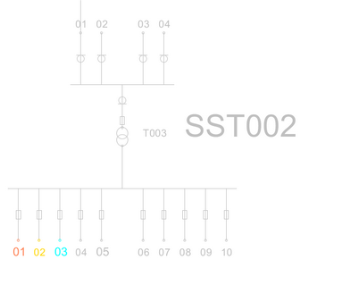
and like this in the schematic view: