Calculation functionality to calculate the sum of capacitances in islands/zones delimited by breakers, disconnectors and other switches.
The function is started from the main calculation form after a trace of a medium voltage network.
Select Capacitive zones as Network calculation type when starting the calculation.
The zones limits are defined by available switches. The type of switches used can be modified in a configuration file. As a standard the following switches are defined to limit the zone:
Breakers and Line breakers
Disconnectors and line disconnectors
Other disconnecting device of object category type Simple connector and Line ditto.
Result presentation
The following result terms are available:
Zone number
ID for a zone, this number is system generated. A zone is an island limited by switches.
Sum capacitive earth fault currents, A
The sum of capacitive currents generated by a cable network in a zone.
Sum reactor currents, A
The sum of reactor generated currents in a zone
Sum resistor currents, A
The sum of resistor generated currents in a zone
Sum other capacitive currents, A
The sum of other measured capacitive earth fault currents for a zone.
Visualization col.numb
A numeric value that can be given up to 5 values. Is used for presentation colors in the templates, below.
Theory
Note! For the moment there is only a small part implemented of what the theory part describes.
The theoretical part is presented in its entirety as the context is otherwise lost if only current parts are included.
Control of earth fault currents when sectioning distribution networks
Basic model
- An overview model based on what can be called sectioning zones, as units.
A zone is defined as the smallest network part that can be isolated from the rest of the network of sectioning devices, illustrated in Fig. 1a. Zoning is used in reliability calculations in distribution systems:
Gunnar Wåglund, Svenska Kraftnät, degree project late -70
A. Mäkinen, E. Lakervi, Tampere University of Technology, PSCC Conference Report, Graz, Austria, -90
Y. Backlund, concept for model for reliability calculation in distribution systems, -98
- The model makes an automatic division of the network into zones and zone configuration, based on the location of switches and sectioning devices in the network and their status (open / closed).
- The model proposal here consists of two steps. In step 1, the network's fault current data is read in Facil's database. Based on line lengths and zero-sequence capacitances per unit length as well as the zero points (incl. Local) type and impedances as well as locations in the network, the model automatically builds up the system of zones.
Within each zone, its share of the network's earth fault admittances and and earth fault currents is summed:
a) YC0 = 3wSC0 , YLn = S(1/(wLn)) , YRn= S(1/Rn) (incl. coil resistive losses)
b) IC0 = VR0 YC0 , ILn = VR0 YLn , IRn = VR0 YRn
c) Izon= IRn + j( IC0 - ILn ), the resulting contribution of the zone to the earth fault currents
VR0 is the phase voltage before a fault occurs. The note n stands for zero point including local. IC0 may include other measured capacitive current.
Additional model
When the zone system and its currents 1) have been calculated in step 1, one proceeds to step 2 and the system model according to Fig. 1b. You can then do re-sections (incl. Disconnections) and earth fault checks in this system.
In the event of a fault in a zone k, one can e.g. choose to calculate the earth fault currents:
1) total for the system
2) total for each radial, incl. the grounded
3) from underlying zones
4) from the above zones, incl. the grounded
5) out on the grounded radial
The earth fault currents b) above refer to mute earth fault and are scaled down when an impedance is introduced in the fault location.
- When you make a new calculation, you go directly to step 2. Only if you have changed the original network, you need to run step 1 again.
- A new sectioning is specified, start step 2 which loads the sectioning and calculates the new earth fault currents.
The earth fault currents can be calculated with the approximate equivalent,
by appendix 1, extended with information that the zoning system provides the opportunity in connection with the sectionings.
- The zone system according to Fig. 1b and its data are stored in Facil, ev. together with the original network, and possibly exported to other computer systems where step 2 can be run.
Sub model
The model above can be limited to step 1, ie the basic model for building the zone system. Printouts of results from this can be suggested as follows:
1. Zone number and identity, where the identity is retrieved from the database
2. Zone admittances and currents according to a) - c) above.
3.Closest to the above sectioning device and its identity
4.Closest to the above zone with number and identity
5. Surrounding sectioning devices and their identity and status open / closed.
6. Open sectioning device refers to the possibility of reserve feeding / re-sectioning.
7.For further description of the zone's delimitation to the rest of the network, all sections and nodes within the zone are printed out.
8. Steps 1-7 are repeated for each zone.
9. When all zones in the network have been printed, a graphical image of the network and its zone system in the form of the tree structure according to Fig. 1b can be presented. Furthermore, it is conceivable to color mark the zones in a network image based on information from step 7.
10. The zoning starts with the entry point and its central compensation as zone no. 1
The system representation according to Fig. 1b could perhaps also be used in a location model for locations and dimensions of local compensation.
Appendix 1.
Calculation of earth fault currents with approximate model
(Relay protection for distribution networks. Application guide. ASEA RELAYS 1985)
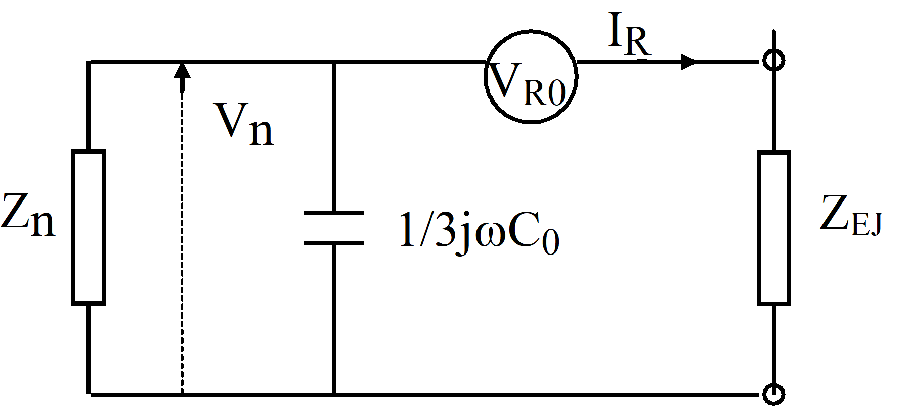
Fig. 1.1 Approximate equivalent for single-phase earth fault
Obtained from the equivalent is:
IR = VR0/(ZEJ + Z’n) (1.1)
where
1/ Z’n = 1/Rn + j(3wC0 - 1/wLn) (1.2)
Rn also includes, in addition to zero point resistors, resistances representing zero point resistive resistors, including relocated.
Ln also includes inductances for relocated zero point reactors
C0 also includes measured other capacitive current, including in out-located
zero points, converted to capacitances at nominal voltage
The zero point (zero sequence) voltage becomes
Vn = - IR*Z’n = - VR0/( ZEJ /Z’n + 1) (1.3)
= - k*VR0
where
k = 1/( ZEJ /Z’n + 1) (1.4)
With negligible grounding impedance ZEJ, the factor is k = 1.
The earth fault current division by radial is illustrated by Fig. 1.2
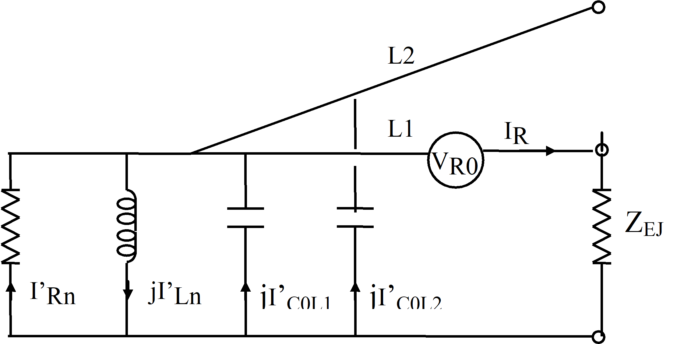
Fig. 1.2 Distribution of the earth fault current per radial
In the event of a fault on radial L1, the protection of the pipes by the currents is passed.
L1) I’L1 = k IL1 = k (IRn- IRnL1 + j( IC0 - IC0L1 - ILn + ILnL1)) (1.5)
L2) I’L2 = k IL2 = - k ( IRnL2 + j(IC0L2 - ILnL2)) (1.6)
Where power contributions also come from localized zero points, including active reactor losses and measured other capacitive currents.