Right click menus
There are several functions that can be reached by using the right-click menu when an object is selected. The menu alternatives can vary depending on the object type. Some examples are listed below.
Right click menu for Route
When you right-click on a route, a right-click menu is opened.
In the right-click menu it is possible to for example Show cross section and Change state and Place cross sections for routes.
Place cross sections for routes
When using the Place cross sections for routes function, it is possible to place multiple cross sections at the same time without having to manually position them in the map. When the function is activated, the Place cross sections for routes window opens.
Here, checkboxes and radio buttons can be used to choose how the cross sections should be placed in the map. By default, the options Place only for route without an existing cross section, Place a cross section in the middle of the route, and Place in the north direction will be pre-selected.
It is possible to check multiple checkboxes, but for the radio buttons, only one can be selected at a time, as they determine the direction of the cross section.
|
When selecting the direction (north, west, south, east) for the cross section, this applies only to new cross sections. Existing cross sections will not be affected by the chosen direction. This function cannot therefore be used to change the direction of already existing cross sections. |
When you are satisfied with the settings, press OK to start placing the cross sections.
Once the function has completed, the cross sections will have been automatically placed for the selected route.
If multiple routes need to be selected, it is recommended to use the Select with dialog function, which can be found in the toolbar or under Edit > Select > Select with dialog.
For more information about this function, see the section Select with dialog.
Right-click menu for objects
Address functions
•The function Get address (Lantmäteriet) gives ability to apply address information from Lantmäteriet to an object, based on UUID. The four address fields are updated: Street Address, Postal Code, Town, and Municipality. UUID is prioritized and used if available, otherwise coordinates are used.
|
Any existing values in the address fields will be overwritten. |
•The function Get property information (Lantmäteriet) gives ability to apply property information from Lantmäteriet to an object, based on its coordinates. The two property fields are updated: Property designation, and UUID property.
|
Any existing values in the property fields will be overwritten. |
|
•Applies only to documentation within Sweden •Access to the 'Belägenhetsadress Direkt API' (username and password)is required. |
Right-click menu for Cable
In the right-click menu, you can for example Show cable route, Change state and Create product specification.
When using the Show cable route function, it is possible to graphically display the cable route of the cable. It is possible to show the cable route in Active view, in another view and in a new window.
Show cable paths
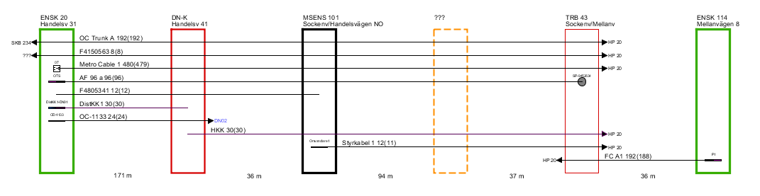
Show schematic map of cables and pipes along the route path by using right-click a route path folder and select Show cable paths or Show pipe paths. A diagram opens in a new window:
Press F5 to put out the highlighted diagram.
•The diagram displays all nodes that forms the selected route path, starting node to the left, end node to the right, and in between all intermediate nodes. Between the nodes the route length is shown.
•Cables running entirely or partially along the route path are displayed as lines, with a text label showing ID, number of fiber or threads, and - in parenthesis - number of unoccupied fibers/threads, i.e without a service or connection.
•If the cable is connected to any equipment in any of the nodes, this is also displayed. If the cable branches off, this is shown with an arrow symbol and the ID of the node that the cable is running towards (Note! This is not always the same node as the one the cable ends in).
•For Show pipe paths, pipes and ducts rather than cables are shown in the diagram. The layout is very similar to that of the cable but this diagram opens up a couple of interesting use cases.
oIf a cable is to be placed in a sequence of pipes/ducts in order to reach its intended destination, the find route path can be run with the intended start and end for the cable as start and end nodes. The show pipe path diagram can then be used as a guidance for finding the sequence of suitable pipes/ducts. By using the command Put cable/pipe in route/pipe the cable can be extended step by step along the path, using the available pipes and ducts.
oIf the Find route path is run with the start node at the start of a multiduct and the end at the end of that multiduct, the diagram shows a nice overview of the ducts in the multiducts, including the ducts as seen from the end node.
Show compact cable path
The function works the same way as using Show cable path with the difference that the Show compact cable path function excludes existing Event nodes, resulting in a more compact schematic view. For cables, the function is available from the right-click menu > Show compact cable path.
Related data
Endpoint lines
Cables and services can have a line in the map that is a straight line between its end-points. This line is generated with the command Create endpoint line available in the right-click menu under Related data.
If several cables/services share the same endpoints, the generation of the endpoint lines will result in overlapping lines. If that is not desired, the lines can be adjusted by adding one or more vertexes to the line. Such an edit should preferably not change the ends of the line.
When the command Create endpoint line is applied to a cable/service that already has an end-point line, the line is first controlled with respect to the position of its ends. If those match geographically with the nodes that the cable really ends in, nothing is done. Please note that just the ends are checked, a line with additional vertexes will remain untouched as long as the ends match the nodes. If the ends don't match the line is redrawn as a straight line.
Geographical layout lines
Cables, pipes/ducts and multiducts can have geographical layout lines in the map that shows the actual layout of the object. These lines are placed by the command Generate geographical layout line that is available in the right-click menu under Related data.
The generated line will follow the routes that the object is directly or indirectly present. The layout needs to be in a continuous stretch of routes without any forks or gaps. Small gaps between the route and the connected node are allowed and the tolerance is specified in Tools > Settings.
The lines are not automatically updated if changes are made to the object or to any of the route parents. Instead, the tools Check geographical layout line and Update geographical layout line can be used for that purpose.
For the multiduct there is an additional layout line, original geographical layout line. When a multiduct has been put in real use, it is typically split in many places in order for the microducts to be split and connected to single ducts feeding the end-points. In order to show the layout of the multiduct as it is stretched out the command Generate original geographical layout line will generate a line for the combination of all of the split up multiduct objects. The line component will be a component of one of the multiduct segments. Similar to the normal geographical layout line, the line is not automatically updated. Instead, the tools Check original geographical layout line and Update original geographical layout line can be used for that purpose.
Link cable to a product specification
1.Open the Query Tool and select Search > Opto > Cable.
2.Select the cable to link and right-click.
3.Choose Related data > Select product specification.
4.Click Search in the dialog box.
5.Select the desired product specification from the list and click OK.
6.If the cable already has a linked product specification, you will be prompted to confirm whether you want to continue. Click OK. The link will be created.
Link multiple cables to a product specification
1.Open the Query Tool and select Search > Opto > Cable.
2.Select the cables to link and right-click.
3.Choose Related data > Select product specification.
4.Click Search in the dialog box.
5.Select the desired product specification from the list and click OK.
6.Choose whether the product specification should:
a.be applied to all selected cables, or
b.only to cables that lack a connection.
7.Click OK to create the links.
Generate [underlying object]
The function generates underlying objects based on the selected object type. The type of object created depends on which object the function is applied to (e.g., fiber, ducts, or connectors). The function can be used on one or multiple objects at the same time.
1.Open the Query Tool and search for an object type in the Search tab.
2.Select the object(s) for which you want to generate underlying objects in the result list, then right-click.
3.Choose Related data > Generate [underlying object]. Underlying objects will then be created for the selected objects.
a.If the underlying objects require adjustments before they can be generated, a dialog box will appear with information that you need to confirm.
b.If some of the selected objects are locked by another user, you will receive a message allowing you to skip those objects.
Links
Administrate contacts
In the right click menu for distribution nodes, under Links > Administrate contacts you can create or/and link a contact person.
Link distribution node to technical shed
In the right click menu for distribution nodes, under Links > Link distribution node to technical shed you have the ability to create mirror objects in dpCom for distribution node, corresponding to the object Technical Shed in dpPower. After linking, updates to location and certain attributes are synchronized.
Link pole to radio tower
In the right click menu for poles, under Links > Link pole to radio tower you have the ability to create mirror objects in dpCom for Pole, corresponding to the object Radio Tower in dpPower. After linking, updates to location and certain attributes are synchronized.
Drawings
|
Requires the Drawings module. |
Place on drawing
Places a component in a drawing and automatically creates a link between the component and the object in the drawing.
Associate object with drawing
Links an object to a drawing.
Generate drawing
Creates one or more blank drawings based on the selected drawing type for each marked object. Certain objects (e.g., dpCom nodes) automatically link to additional objects (e.g., node content).
Show associated drawings
Opens the drawings linked to the object in the drawings editor.
Show drawings preview
Displays the drawing in the main application as a read-only preview. The user can use most of the tools available in the main application also in the preview.