Use the patch chain tool to build a physical chain of fiber paths between two locations via intermediate nodes. In practice, this means creating a number of patches in or between ODF units in one or more nodes along a connection path. The tool includes functions to trace and filter connectors and fibers of specified type and quality. The map support makes it possible to visualize and select the next desired node in a planned fiber chain in the map. Furthermore, the tool provides the possibility to link a service to a fiber chain, as well as to link a fiber chain to other fiber chains to mark the desired redundancy on connections. It is also possible to link to a fiber chain directly from the connection's attribute form.
The patch chain tool is used as a powerful alternative to, in the map, opening and patching in each node along a desired progress path between two points. For that method, you use the Patch fiber tool instead.
When you have created a fiber chain, you can use the Query Tool or the Search tab in the sidebar via the fiber chain's unique Chain Code ID to search for and highlight it in the map.
Currently there is no graphical representation of patch cables. This means that patches that you have created in the patch chain tool do not appear in, for example, fiber diagrams. However, it is possible to easily generate a so-called fiber patch report that reports all patch cables on selected fiber connections.
Prerequisites
•Before you start patching in the tool, verify that there are contiguous connections along the desired route path by performing a trace from contacts in ODF devices in the intended start node, to the intended end node.
Create a fiber chain
1.Select Edit > Fiber > Patch Chain Tool (P) or select ![]() in the toolbar.
in the toolbar.
2.In the graphical view, select a node or ODF where the planned fiber chain should start. The patch chain tool opens.
3.Enter any criteria for the fiber chain (Fiber and Contact type, Maximum length and Attenuation) in the Main information field at the top left of the tool window.
4.In the field Current node at the bottom left of the tool window, the field header shows which node we are currently in. The table shows the ODF units that are in the node.
5.Select one or more ODFs. In the Contacts field, all contacts in the selected ODF are now displayed, with information on how they are connected via fibers to adjacent nodes in the network.
6.Use the filter options below the connector table to display connectors/fibers of a certain type and quality.
7.In the Parent ID column to the right of the table, identify the node/rack/device you want the fiber path to go to. Then select the appropriate fibers going to the desired node. Left-click and mark the fibers in the table. (Press Shift and Ctrl to select multiple fibers/connectors). Remember that a fiber chain must consist of an even number of fiber paths, and that the fibers in each step must end at the same node.
8.After selecting the appropriate fibers/connectors, press Connect. In the chain tables in the Fiber Panel, the first step in the fiber path is now created. Note that no patching has yet been created.
9.In the tool, notice that the field heading in Current Node is updated. Now the next step in the fiber chain will be built using the location map.
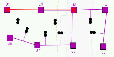
10. Select any units in the current node and then press Show in map... The map displays the current and adjacent nodes. Red crosses mark the nodes that are connected to one of the selected ODF units and are therefore candidates to form an end node in the next step in the fiber chain.
|
Possible fiber paths in the image example shown above are J1 and J3. J3 is an appropriate choice, as J1 would mean that the fiber path returns to where the fiber chain begins. |
11. Select one of the highlighted nodes in the map. The contact table in the Patch Chain tool now contains all valid contacts in all the tracked nodes. Contacts in the selected node in the map are highlighted in yellow. Select the Show only selected node [node-id] checkbox to hide other contacts.
12. Select two fibers/connectors and then press Connect.
13.The chain tables show that a next step in the fiber chain has been built.
14. Now it is just a matter of continuing with the other steps, in order to finally reach the desired node, which can for example consist of a customer connection. Press OK or Apply to save new or changed patching.
Settings in the Patch Chain Tool window
The functions of the patch chain tool are divided into the fields Main info, Redundancy, Node, Connectors and the Fiber Panel.
Fields
Main info Contains information about the fiber chain ID, linked services, and allows you to specify basic criteria for the fiber chain which can be used for creating fiber paths with a specified quality of incoming connectors and fibers. |
||||||||||||||||||
|
||||||||||||||||||
Redundancy The field contains two tables showing fiber chains which you have linked to the current fiber chain to plan redundancy with the goal of protecting against outages in nodes along a connection. Fully redundant chains are linked fiber chains that do not share any intermediate node with the current fiber chain, only the start and end nodes are common. Redundant chains share at least one node with the current fiber chain. To link or unlink redundant chains, press the Redundancy button. Linked fiber chains that do not meet the requirements for redundancy are marked in red. |
||||||||||||||||||
Node The field header shows the current node. The table shows the devices that are in the node, with information about Type and Id. When you select one or more devices, all of the device's contacts are displayed in the Contacts table. |
||||||||||||||||||
Connectors Contains a table of the contacts included in selected devices in the table in the Current node field. Only connectors that have connected fibers are shown in the table. Select connectors (fibers) and then press Connect. The contacts are added to the chain tables in the Fiber panel. At the bottom of the field is a legend and options to hide and show connectors and fibers of a certain type or quality:
|
||||||||||||||||||
Fiber panel Contains information about length, attenuation, fiber steps and patching for each fiber path in the fiber chain. Four fiber paths can be presented simultaneously. If the fiber chain contains more than 4 fiber paths, they can be accessed using a drop-down list at the bottom of the panel.
|
The chain tables at the bottom of the panel show each step in the fiber paths that together form a fiber chain. Each new step is shown in a different color (white/grey). Between each step a patching has been performed.
When you link selected contacts in the Contacts field, they are added to the bottom of the chain tables. If you press Disconnect, it is always the step at the bottom of the tables that is removed. It is possible to reverse the chain in the tables, see the Reverse chain button.
Buttons
Connect |
Connect selected contacts. The Connect button is grayed out and cannot be activated unless the connection rules are met. Hover over the button to display a balloon text describing the error:
"Used in this chain" A connector/fiber can only be used once in a fiber chain. The chain tables in the Fiber panel field show which connectors (and connected fibers) are part of the fiber chain.
"Wrong number of fibers" ▪Fibers (connectors) must be selected in pairs; 2, 4, 6, 8, or 10, etc. ▪Each step in a fiber chain must contain the same number of fibers: 2 -- 2 -- 2 or 4 -- 4 -- 4 -- 4, etc. See Number of fibers in the Main info field.
"Not the same endpoint or no endpoint" The fibers (on the selected connectors) must all be connected in the same end node. However, they do not have to be connected to the same device/rack.
When all the rules are met, the Connect button becomes active and you can connect the selected fibers.
|
Disconnect |
Disconnect the bottom (last) step in the chain tables. |
Service |
Opens the Search for service to link window where you have the option to create a new one or search for and select an existing service to be linked to the fiber chain. The service name is printed in the Service field in Main info at the top left of the tool window. Press Service to remove an existing service. |
Redundancy |
Opens a dialog box where you have the option to search for and connect/disconnect other fiber chains of a specified redundancy. See further description field Redundancy. |
Show in map |
Allows you to select a node in the map that will be the next step in the fiber chain. Possible/valid nodes are tracked and highlighted based on the devices you first select in the Current Node field. See the example in Create a fiber chain below. |
Reverse chain |
Reverses the order of the steps in the chain tables in the Fiber panel. It makes it possible to connect or disconnect steps at any end of the fiber chain and thus change the fiber chain's route and in which way devices are patched. |
OK |
Saves changes and closes the tool window. |
Cancel |
Cancels and closes the tool without saving. |
Apply |
Saves changes without closing the tool window. |